This guide explains calculating breaker interrupting capacity per NEC for safe electrical system design operation.
Includes formulas, tables, and worked examples to determine minimum interrupting ratings at distribution switchgear locations.Breaker Interrupting Capacity (kAIC) Requirement Calculator — NEC Guidance
Background and code requirements for interrupting capacity
NEC requirements and definitions
The National Electrical Code (NEC, NFPA 70) requires overcurrent protective devices and equipment to have an interrupting rating sufficient for the available fault current at their point of installation. Key code excerpts used by designers include:- NEC 110.9: Equipment intended to interrupt current at fault conditions shall have an interrupting rating not less than the available fault current. - NEC 240.86 and related sections: Requirements for marking and selection of overcurrent devices in specific applications (verify latest code edition text for exact cross-references).Practical interpretation: Select a breaker whose interrupting capacity (kA or A symmetrical at specified voltage) equals or exceeds the maximum available symmetrical fault current that can appear at the device terminals.Fundamental electrical concepts used in calculations
Basic definitions
- Available fault current (Isc): The prospective symmetrical current that can flow during a bolted three-phase fault at the point of consideration.
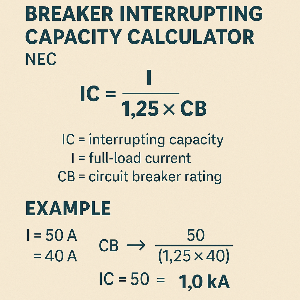
- Interrupting capacity (IC): The maximum current magnitude a breaker is certified to safely clear without catastrophic failure; often expressed as symmetrical kA RMS.
- Thevenin equivalent: Represents remote supply as an ideal voltage source with series impedance; used to compute local fault currents.
- %Z (transformer impedance): Per cent impedance of a transformer, used to compute short-circuit contribution from transformer secondary.
Typical assumptions and approximations
Designers commonly assume:- Balanced three-phase bolted faults are used to compute symmetrical currents.
- Transformer %Z is given at nameplate and used to calculate available secondary fault current ignoring X/R effects unless asymmetry must be considered.
- Line/cable impedance is modelled as series phase impedance (R + jX) for the conductor path between source and fault.
Core formulas and variable explanations
Full-load and short-circuit current at transformer secondary
Use basic transformer relationships for balanced three-phase systems.Full-load current (I_FL):- kVA: transformer rated kVA (e.g., 75, 150, 500 kVA)
- V_LL: transformer secondary line-to-line voltage (e.g., 208 V, 480 V)
- Z%: transformer's percent impedance (typically 4%–8% for distribution transformers; see transformer nameplate)
Fault current from Thevenin equivalent and series impedance
When a source with Thevenin voltage E_th (line-to-line) and series phase impedance Z_total (ohms per phase) feeds a three-phase fault:- V_LL is nominal line-to-line voltage at the point of calculation (volts).
- Z_total is phase impedance to the fault point (ohms) including transformer equivalent impedance referred to the same base and conductor/cable impedance.
Z_ohms = (Z% / 100) × (V_LL2 / (kVA × 1000))
(for transformer equivalent impedance converted to ohms on the secondary base)Combining multiple sources
If multiple sources (utility + generator + transformer) contribute, the superposition of symmetrical currents is not strictly additive because of phase relationships and X/R ratios. Practical methods:- Convert each source to Thevenin impedance per phase (Z1, Z2, ...), then compute total parallel Thevenin impedance: Z_total = (Z1||Z2||...)+Z_line_to_fault.
- Then compute I_SC = V_LL / (√3 × Z_total).
Tables of common values for quick calculator inputs
| Common Transformer kVA | Typical %Z Range | Typical Full-Load Current (480 V) | Typical Full-Load Current (208 V) |
|---|---|---|---|
| 75 kVA | 4%–6% | 90.3 A | 208.6 A |
| 150 kVA | 4%–6% | 180.6 A | 417.1 A |
| 500 kVA | 4%–8% | 602.9 A | 1390.4 A |
| 1000 kVA | 4%–8% | 1205.8 A | 2780.8 A |
| Common Breaker Interrupting Ratings (Symmetrical) | Typical Voltage Rating | Common Use |
|---|---|---|
| 10 kA | 120/240 V | Residential single-phase, small panels |
| 22 kA | 240–480 V | Small commercial, some 3-phase panels |
| 65 kA | 480 V | Typical industrial distribution breakers |
| 100 kA | 480–600 V | Large service and switchgear |
| 200 kA | 600 V+ | High fault current installations, critical systems |
| Conductor Impedance per 1000 ft (approx.) | AWG / Size | R (Ω/1000 ft) | X (Ω/1000 ft) |
|---|---|---|---|
| Copper 3/0 | 3/0 | 0.049 | 0.061 |
| Copper 250 kcmil | 250 kcmil | 0.031 | 0.050 |
| Aluminum 500 kcmil | 500 kcmil (Al) | 0.035 | 0.050 |
| Copper 4/0 | 4/0 | 0.049 | 0.060 |
Step-by-step algorithm for a breaker interrupting capacity calculator
Use this algorithm to implement a calculator or to perform manual calculations:- Gather inputs:
- Transformer kVA and %Z (from nameplate).
- System voltage (line-to-line) at the point of calculation.
- Utility available fault current at point of service (if provided).
- Conductor and cable lengths and sizes from source to device.
- Any parallel sources (generators) or switchgear with known impedances.
- Compute transformer full-load current:I_FL = (kVA × 1000) / (√3 × V_LL)
- Compute ideal transformer secondary short-circuit current:I_SC_transformer = I_FL × (100 / Z%)
- Convert transformer %Z to ohms on the secondary base and sum with conductor impedance to compute Z_total to fault:
Z_transformer_ohm = (Z% / 100) × (V_LL2 / (kVA × 1000))

Calculator Breaker Interrupting Capacity Calculator Nec for Accurate Short-Circuit Ratings Z_total = Z_transformer_ohm + Z_conductor + Z_other_sources_referred - Compute available fault current at the fault point:I_SC = V_LL / (√3 × Z_total)
- Compare computed I_SC (symmetrical RMS) with candidate breaker interrupting rating. Ensure breaker rating ≥ computed I_SC at the system voltage.
- Document assumptions (X/R, ungrounded vs grounded, utility maximums) and apply safety margin where appropriate (NEC requires rating not less than available current; many designers use the computed value or next higher standard rating).
Worked examples (realistic scenarios)
Example 1 — Transformer-limited available fault current at 480 V
Problem statement: A 500 kVA padmount transformer supplies a 480 V three-phase distribution bus. Nameplate %Z = 5.0%. What is the prospective symmetrical short-circuit current at the transformer secondary terminals? What minimum breaker interrupting rating is required at that bus?Step 1 — Compute full-load current:I_SC = I_FL × (100 / Z%) = 601.7 × (100 / 5.0) = 601.7 × 20 = 12,034 A
Result:- Prospective symmetrical fault current at transformer secondary ≈ 12.0 kA RMS.
- Minimum breaker interrupting rating required: ≥ 12.0 kA at 480 V.
- Standard breaker ratings: 10 kA (insufficient), 22 kA (suitable). Select a breaker with 22 kA interrupting rating at 480 V (or higher certified rating) and document the basis per NEC 110.9.
Example 2 — Feeder impedance reduces available fault at remote panel
Problem statement: Same 500 kVA, 480 V transformer, Z% = 5.0%. A 200-foot copper 250 kcmil feeder (one-way) feeds a motor control center. Estimate the available fault current at the MCC feeder lugs. Use approximate conductor impedance values from table (R = 0.031 Ω/1000 ft, X = 0.050 Ω/1000 ft). Assume three-phase balanced bolted fault and neglect other sources.Step 1 — Transformer equivalent impedance in ohms (per phase) referred to secondary:Z_transformer_ohm = (Z% / 100) × (V_LL2 / (kVA × 1000))
Plug values:Z_transformer_ohm = (5 / 100) × (4802 / (500 × 1000))
Calculate numerator:4802 = 230400; 230400 / 500000 = 0.4608
Then:|Z_feeder| = √(0.00622 + 0.01002) ≈ √(0.00003844 + 0.0001) ≈ √0.00013844 ≈ 0.01178 Ω
Step 3 — Total phase impedance to fault:I_SC = V_LL / (√3 × Z_total) = 480 / (1.732 × 0.03482) = 480 / 0.0603 ≈ 7960 A
Results and selection:- Available symmetrical fault current at MCC ≈ 7.96 kA (reduced from 12.0 kA at transformer secondary due to feeder impedance).
- Minimum breaker interrupting rating at MCC = ≥ 7.96 kA. Standard breaker rating options: 10 kA (suitable), 22 kA (higher).
- Because NEC requires device interrupting rating not less than available fault current, a 10 kA breaker rated at 480 V would meet the requirement in this case.
- Document conductor lengths, impedance assumptions, and rounding conventions used in the calculation.
Example 3 — Parallel sources (utility + generator) simplified approach
Problem statement: A facility has a utility service that, at the point of service, can deliver 5 kA available fault current at 13.8 kV. A step-down transformer (1500 kVA, 4% Z) supplies 480 V distribution. A standby generator is connected through switchgear; during paralleling, generator contributes additional short-circuit current such that its equivalent Thevenin impedance is Z_gen = 0.08 Ω on the 480 V base. Determine a conservative estimate of available fault current at main distribution bus when both sources are in service.Step 1 — Convert utility contribution to 480 V base via transformer ratio or convert transformer equivalent impedance; a practical conservative approach is to compute Thevenin impedances and parallel them on the same base. For simplicity, compute transformer-based current first and then combine with generator:Compute transformer full-load current at 480 V:- Request utility available fault current data at point of service (recommended by NEC commentary);
- Obtain generator subtransient reactance X"d and convert to equivalent Z on 480 V base; then compute Z_total = (Z_utility_ref + Z_transformer + Z_feeder) || Z_generator; finally compute I_SC = V_LL / (√3 × Z_total).
Practical selection rules and documentation
When choosing breakers and documenting calculations:- Always use the highest computed available fault current at the point of installation for selection.
- Round calculations conservatively; if computed I_SC = 12.0 kA, select a breaker rated ≥ 12.0 kA; typically the next standard is 22 kA for industrial breakers.
- Marking: NEC 110.9 requires the interrupting rating to be marked on equipment. Ensure the selected breaker listing/certification includes the voltage and interrupting rating for the application.
- Record sources of input data: transformer nameplate, utility fault current letter, conductor data, and calculation assumptions.
Design considerations affecting calculator accuracy
- X/R ratio: High X/R increases DC offset and peak asymmetrical currents; many breaker ratings are given in symmetrical RMS kA and include asymmetry considerations in manufacturer data.
- Motor contributions: Large motors can contribute to fault current for a short time and may increase asymmetrical components—include motor contribution where required by standard practice.
- Parallel sources and neutral grounding: Grounding affects line-to-ground fault currents; this article focuses on three-phase bolted fault symmetry.
- Utility data variability: Utility can supply maximum and minimum fault current values—designers should use the maximum available for protective device interrupting rating selection.
Implementation tips for an online calculator
- Input validation: Require nameplate fields (kVA, %Z, V_LL), conductor sizes and lengths, and utility fault current if available.
- Units: Use consistent units (kVA, volts, ohms, feet/meters) and provide unit conversion helpers.
- Output: Provide computed I_FL, transformer I_SC, Z_total (ohms), I_SC at device point, and recommended minimum breaker interrupting rating with a list of standard available ratings.
- Report generation: Produce a printable calculation report that includes assumptions, references (NEC section cited), and recommended device listings.
References and authoritative resources
- NFPA 70, National Electrical Code (NEC) — official publication for electrical installations: https://www.nfpa.org/NEC
- NEC Article 110.9 — Requirements for interrupting ratings (refer to the current code edition for exact text): https://www.nfpa.org
- IEEE Std 141 (IEEE Green Book) — grounding and system analysis guidance: https://standards.ieee.org/standard/141-1993.html
- IEEE Std 399 (IEEE Brown Book) — industrial power system analysis: https://standards.ieee.org/standard/399-1997.html
- NEMA and manufacturer technical guides for breaker interrupting ratings and test criteria (consult product datasheets and UL/ANSI listings): https://www.nema.org
- Utility short-circuit contribution practices — consult local utility procedures and available fault current letters.
Best practices and checklist
- Collect nameplate data and utility fault current letter before finalizing breaker selection.
- Compute both transformer-limited and feeder-reduced available fault currents; use the larger value at the point of installation.
- Consider the effect of parallel sources, motor starting contributions, and grounding when applicable.
- Specify breakers with documented, tested interrupting ratings at the system voltage per manufacturer and listing agency (UL/ANSI).
- Keep clear documentation of assumptions, calculation steps, and references for code compliance and future maintenance.