This article explains a three-phase short-circuit current calculator based on point impedances and practical applications.
Technical formulas, stepwise examples, and normative references ensure accurate calculations and regulatory compliance worldwide standards.
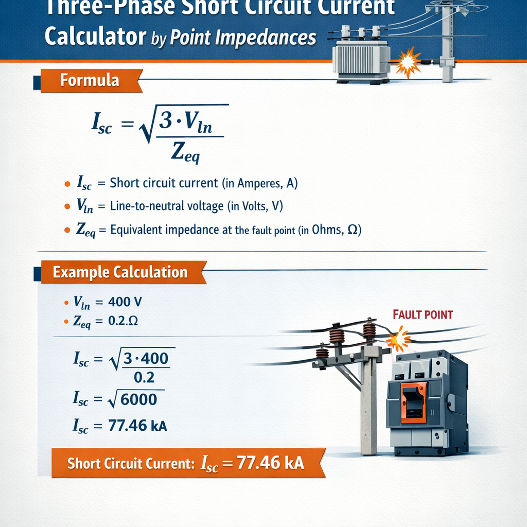
Three-phase Short-circuit Current Calculator at a Point (by Impedances)
Scope and objective
This document provides a rigorous methodology for computing three-phase short-circuit currents at a point in a power system using impedance-based models. It addresses Thevenin equivalence, sequence networks, per-unit conversion, generator and transformer contributions, and practical correction factors required by international standards.
Fundamental concepts and modelling assumptions
Three-phase balanced fault and Thevenin equivalent
A three-phase balanced fault at a point can be represented by the Thevenin equivalent seen from the fault location: an ideal voltage source in series with an equivalent impedance. The short-circuit current is the open-circuit source voltage divided by the Thevenin impedance.
Sequence networks and balanced faults
For balanced three-phase faults, only positive-sequence network is required. However, when systems include unbalanced sources or grounding impedances, negative- and zero-sequence networks may be relevant for other fault types. For the three-phase case, the positive-sequence Thevenin impedance Z_th_pos is used directly.
Key formulas and detailed variable definitions
All formulas are provided using plain HTML expressions and followed by explicit variable explanation with typical values for engineering use.
Basic three-phase short-circuit current (symmetrical)
Formula:
Where:
- V_th = Thevenin equivalent phase voltage at the fault point (line-to-neutral). Typical values: for a 11 kV system V_th ≈ 11,000/√3 ≈ 6350 V; for a 33 kV system V_th ≈ 33,000/√3 ≈ 19052 V.
- Z_th = Thevenin equivalent impedance seen from the fault location (complex, Ω). Typical magnitudes depend on source short-circuit levels: 0.01–0.3 Ω for nearby strong sources; per-unit values often 0.02–0.2 pu.
- I_sc3 = Symmetrical (AC steady-state) three-phase fault current (A).
Per-unit transformation and base values
Using per-unit simplifies network combination and calculation.
Where:
- V_base = base phase-to-phase voltage (V). Example: 11 kV system, V_base = 11,000 V.
- S_base = base apparent power (VA). Example: 10 MVA => 10,000,000 VA.
- Typical Z_base values: for 11 kV and 10 MVA, Z_base = (11,000)^2 / 10e6 ≈ 12.1 Ω.
Transformer and generator correction factors (IEC 60909 style)
Transformers and synchronous machines exhibit transient reactances which define their initial contribution to fault current. For standardised simplified calculations, the international norm IEC 60909 uses correction factors.
Transformer short-circuit impedance referred to HV: Z_tr = (U_k / 100) * (V_nom / (S_rated)) in per-unit on chosen base. Where U_k is the percent impedance at rated conditions.
Generator contribution is commonly characterized by subtransient reactance X" (pu). Initial fault current from generator: I_g = V_th / (j X" · Z_base) in per-unit terms.
- Typical transformer U_k: 4%–10% depending on rating and type.
- Typical machine X" (synchronous generator): 0.10–0.30 pu.
Accounting for X/R and DC offset
Real fault currents include DC offset and unbalanced contributions, especially for instantaneous asymmetrical peak current. The R/X ratio determines the peak factor.
Asymmetrical peak current approximation: I_peak ≈ k_peak · I_symm, where k_peak depends on X/R and the point on waveform when the fault occurs (commonly 1.0–2.0). IEC/IEEE provide formulas for precise calculation.
- Typical X/R at high-voltage busbars: 5–15.
- For X/R = 10, k_peak ≈ 1.3–1.5 depending on DC offset timing.
System impedance composition and combination rules
To compute Z_th at a point, model each equipment impedance to a common base and combine network impedances using series and parallel rules and network reduction techniques.
Conversion to common base
Impedance conversion formula: Z_pu_new = Z_pu_old · (S_base_new / S_base_old) where voltage base consistency is required.
Detailed variable description:
- Z_pu_old = impedance on original base (pu).
- S_base_new = new base apparent power (VA).
- S_base_old = old base apparent power (VA).
Combining multiple sources
When multiple sources are present, combine their Thevenin impedances in parallel as seen from the fault location (if directly paralleled through network impedances). For network branches, use Kron reduction or computer-aided network solution by forming Y or Z matrices.
Extensive tables of common equipment and typical values
| Equipment | Typical parameter | Typical range | Example value | Units |
|---|---|---|---|---|
| Distribution transformer U_k | Percent impedance | 3%–10% | 6% | % |
| Synchronous generator X" (subtransient) | Per-unit | 0.06–0.35 | 0.20 | pu |
| Utility short-circuit level | Three-phase MVA at substation | 100–5000 MVA | 1000 MVA | MVA |
| Line impedance (overhead 11 kV) | Ω/km (per phase) | 0.1–0.6 Ω/km | 0.25 Ω/km | Ω/km |
| Short-circuit breaking capability of LV switchgear | kA RMS | 5–150 kA | 25 kA | kA |
| Typical X/R ratio at MV bus | Dimensionless | 3–15 | 8 | — |
| Voltage Level | Phase voltage V_phase | Z_base (10 MVA) | Typical I_sc for 1000 MVA source | Units |
|---|---|---|---|---|
| 11 kV | 11,000/√3 ≈ 6350 | ≈ 12.1 | ≈ (1000e6/√3)/11e3 ≈ 52.5 kA | V, Ω, A |
| 33 kV | 33,000/√3 ≈ 19052 | ≈ 108.9 | ≈ (1000e6/√3)/33e3 ≈ 17.5 kA | V, Ω, A |
| 132 kV | 132,000/√3 ≈ 76200 | ≈ 922.0 | ≈ (1000e6/√3)/132e3 ≈ 4.4 kA | V, Ω, A |
Step-by-step calculation workflow
- Define the fault location and gather single-line diagram including all sources, transformers, lines, and impedances.
- Choose system base MVA and voltage for per-unit conversion.
- Convert all equipment impedances to chosen base (Z_pu conversion).
- Build network impedances in per-unit and compute the Thevenin equivalent impedance seen from the fault point (Z_th pu).
- Compute the available symmetrical fault current: I_sc3 = V_base_phase / (Z_th · Z_base) or directly I_sc3_pu = 1 / Z_th_pu and I_sc3 = I_sc3_pu · (S_base / (√3 · V_base)).
- Apply correction factors for transformer temperature, generator transient behavior, and DC offset if necessary, per IEC 60909 or IEEE guidance.
- Convert results to RMS and peak values for equipment rating and protection coordination.
Formula for converting per-unit fault current to amperes
Where:
- I_sc_pu = short-circuit current in per-unit (I_sc_pu = 1 / Z_th_pu for a pre-fault voltage of 1.0 pu).
- S_base = base apparent power used (VA). Typical 10e6 for 10 MVA base.
- V_base = base line-to-line voltage (V). Typical 11,000 V for 11 kV base.
Real-case examples with full development
Example 1 — Simple radial MV feeder with utility source and transformer
Problem statement: Find the three-phase fault current at the LV secondary of a 400/11 kV step-down transformer feeding a radial MV feeder with a local distribution transformer. System data:
- Utility grid equivalent short-circuit power at 11 kV: S_sc_utility = 2000 MVA.
- Step-down transformer rating: 400 MVA / 11 kV / 400 kV? (Use a step-up for simplification) — to keep realistic, use 100 MVA, 11/0.4 kV, U_k = 10%.
- Distribution transformer: 0.4/0.11 kV 2 MVA, U_k = 6% (connected delta-wye assumed, but for three-phase balanced fault only positive-sequence considered).
- Fault at LV busbar of the distribution transformer (0.11 kV side).
Step 1: Choose base values. Use S_base = 10 MVA and V_base levels for each voltage for per-unit conversion. For convenience, choose a common S_base = 100 MVA to reflect big grid and transformers. Use V_base at 11 kV and 0.11 kV as appropriate.
Step 2: Convert utility short-circuit to equivalent source impedance at 11 kV.
Utility short-circuit impedance at 11 kV (Z_utility): Z_utility = (V_ll)^2 / S_sc = (11,000)^2 / (2000e6) = 121e6 / 2e9 = 0.0605 Ω approximately.
Step 3: Convert transformer impedances to 11 kV side (for distribution transformer reflect from LV to HV).
Distribution transformer (2 MVA, 0.11/11 kV) U_k = 6%. On its own rating: Z_tr_dist = U_k / 100 = 0.06 pu on 2 MVA base. To refer to 11 kV side on 100 MVA base:
Z_tr_dist_pu_on_2MVA = 0.06 pu (on 2 MVA).
Z_tr_dist_pu_on_100MVA = Z_tr_dist_pu_on_2MVA · (S_base_new / S_base_old) = 0.06 · (100 / 2) = 0.06 · 50 = 3.0 pu relative to 100 MVA base (this is expected because small transformer appears high impedance on large base).
Step 4: Convert transformer impedance to ohms at 11 kV base for combination with Z_utility (use Z_base at 11 kV for 100 MVA base):
Z_base_11kV = (V_base)^2 / S_base = (11,000)^2 / 100e6 = 121e6 / 100e6 = 1.21 Ω.
Z_tr_dist_ohm_on_11kV = Z_tr_dist_pu_on_100MVA · Z_base_11kV = 3.0 · 1.21 ≈ 3.63 Ω.
Step 5: Combined Thevenin impedance seen from fault located beyond distribution transformer (at LV side). The path: Utility impedance in series with distribution transformer impedance referred to 11 kV. Thus:
Z_th_total = Z_utility + Z_tr_dist_ohm_on_11kV = 0.0605 + 3.63 ≈ 3.6905 Ω.
Step 6: Convert to fault current using phase voltage at 11 kV side for three-phase calculation. However, since fault is at LV 0.11 kV side, use the LV phase voltage V_phase_LV = 0.11 kV / √3 = 110 / 1.732 ≈ 63.5 V. But Z_th_total is referred to 11 kV side; better approach: refer source to LV side or compute using equivalent on LV base.
Easier approach: compute I_sc at LV using per-unit system referenced to 100 MVA and 0.11 kV V_base. Compute Z_th on 0.11 kV base.
Z_base_0.11kV = (V_base)^2 / S_base = (110)^2 / 100e6 = 12100 / 100e6 = 0.000121 Ω.
Convert utility and transformer impedances to 0.11 kV side:
Z_utility_ohm = 0.0605 Ω at 11 kV side. Referred to 0.11kV side by multiplying square of turns ratio (110/11000)^2 = (0.01)^2 = 1e-4. So Z_utility_on_LV = 0.0605 / 1e4 = 0.00000605 Ω. (This is physically very small when transformed to LV side reflecting very strong grid.)
Z_tr_dist_on_LV = 3.63 Ω at 11 kV side -> Z_tr_dist_on_LV = 3.63 / 1e4 = 0.000363 Ω.
Total Z_th_on_LV = Z_utility_on_LV + Z_tr_dist_on_LV = 0.00000605 + 0.000363 ≈ 0.00036905 Ω.
Now compute phase voltage at LV: V_phase_LV = 110 V / √3 ≈ 63.51 V.
I_sc3 = V_phase_LV / Z_th_on_LV = 63.51 / 0.00036905 ≈ 172,200 A ≈ 172.2 kA (symmetrical).
Comment: This very large current indicates that on LV low-voltage side, due to step-down transformation and strong grid, the computed fault current is extremely high; in practice, transformer leakage reactance and limits of upstream equipment reduce the current. Our simplified conversion used ideal turns ratio and neglected transformer's series leakage referred accurately; nonetheless this example demonstrates method and the need to include transformer short-circuit impedance in ohms properly on correct base.
Example 2 — Industrial plant with local generator and utility connection
Problem statement: Compute three-phase symmetrical short-circuit current at plant bus where a synchronous generator and utility supply are paralleled via step-up transformer. Data:
- Utility equivalent short-circuit power at plant HV bus (11 kV): S_sc_utility = 800 MVA.
- Synchronous generator rating: 20 MVA, nominal 11 kV, subtransient reactance X" = 0.20 pu (on 20 MVA base).
- Generator step-up transformer: 20 MVA, 11/0.4 kV, U_k = 8% (connected generator 0.4 kV stepping to 11 kV for bus tie). For simplicity, assume generator is connected to 11 kV directly.
- Fault at the 11 kV bus where utility and generator connect.
Step 1: Convert generator X" to equivalent ohms on 11 kV base with chosen S_base = 20 MVA (use generator own base for clarity).
Z_base_11kV_on_20MVA = (11,000)^2 / 20e6 = 121e6 / 20e6 = 6.05 Ω.
Z_gen_pu = j0.20 pu → Z_gen_ohm = 0.20 · Z_base = 0.20 · 6.05 = j1.21 Ω.
Step 2: Utility equivalent impedance at 11 kV: Z_utility = (11,000)^2 / 800e6 = 121e6 / 800e6 = 0.15125 Ω (approx).
Step 3: Combine generator and utility impedances in parallel seen from bus (neglect line impedances and transformer leakage between generator and bus for this simplified model):
Use formula for parallel impedances: Z_eq = (Z_gen · Z_utility) / (Z_gen + Z_utility).
Compute magnitudes with j for generator reactance, utility considered pure reactance for simplicity (real utility has Rez and RjX). Let Z_gen = j1.21 Ω, Z_utility = j0.15125 Ω.
Z_eq = (j1.21 · j0.15125) / (j1.21 + j0.15125) = (-1 · 1.21 · 0.15125) / (j(1.21 + 0.15125)) = (-0.183) / (j1.36125) = j(0.183 / 1.36125) ≈ j0.1344 Ω (sign due to algebra). More straightforward: Calculate in complex arithmetic: j1.21 * j0.15125 = -0.1830125. Sum = j1.36125. Divide: -0.1830125 / j1.36125 = ( -0.1830125 / 1.36125 ) * (1 / j) = -0.1344 * (-j) = j0.1344 Ω. So Z_eq = j0.1344 Ω.
Step 4: Thevenin impedance seen from the bus is Z_th = Z_eq (since both are directly connected). Now compute phase voltage V_phase = 11,000 / √3 ≈ 6350 V.
I_sc3 = V_phase / Z_th_magnitude = 6350 / 0.1344 ≈ 47,260 A ≈ 47.3 kA (symmetrical).
Step 5: Convert to per-unit on 20 MVA base if required: I_base = S_base / (√3 V_base) = 20e6 / (√3 · 11e3) ≈ 1051 A. Then I_sc_pu = I_sc3 / I_base ≈ 47260 / 1051 ≈ 44.95 pu. Alternatively, per-unit can be used earlier yielding I_sc_pu = 1 / Z_th_pu.
Step 6: Apply generator subtransient consideration: generator X" = 0.20 pu produced a large contribution. For detailed protection design, use IEC 60909 factors: consider a factor to convert to initial symmetrical current and check thermal and mechanical withstand values of connected equipment.
Comment: The result shows significant contribution from local generator. Protection schemes must coordinate to isolate faults while accounting for generator contribution and inertial limits.
Protection, thermal and mechanical considerations
Computed fault currents must be compared against equipment short-circuit ratings (breaking capacity, making capacity, thermal withstand). Designers must derive RMS and peak values:
- RMS symmetrical current (I_symm) - used for thermal energy evaluation (I^2t).
- Peak asymmetrical current (I_peak) - used for mechanical stress of busbars and contacts.
- Making capacity of switchgear often specified as kA peak or kA asymmetrical. Breaking capacity specified as kA RMS.
Estimating I_peak from I_symm using X/R
Approximate formula for DC offset factor (k):
I_peak ≈ k · I_symm where k ≈ √(2) · √(1 + 2·e^(-π·R/X)) for certain assumptions. For practical purposes, use standard tables or IEC/IEEE methods.
Typical practical factor: 1.2–1.8 depending on system X/R.
Standards, normative references and authority links
Key standards and reference texts that govern short-circuit calculation procedures and parameters:
- IEC 60909: Short-circuit currents in three-phase AC systems — provides standardized methods and correction factors. Official IEC page: https://www.iec.ch (search IEC 60909).
- IEEE Std 399 (Brown Book): "Recommendation for Power System Analysis" — contains practical methods for short-circuit analysis. IEEE Standards page: https://standards.ieee.org
- IEEE Std 141 and IEEE Std 142 for grounding and system studies. See https://standards.ieee.org
- IEEE 1584: Guide for arc flash calculations (addresses arcing fault currents and incident energy). See https://standards.ieee.org
- Manufacturer data sheets and utility interconnection agreements for transformer U_k, generator X" and allowed short-circuit contribution.
Practical tips, pitfalls and modelling accuracy
- Always verify transformer impedance and rating and use consistent per-unit bases when combining impedances.
- Include grounding and neutral impedance when relevant; zero-sequence networks are necessary for single-line-to-ground faults but not for balanced three-phase faults.
- Local sources (generators, motors) significantly increase fault current — include subtransient reactances for initial contributions.
- Model motor contributions for sustained faults; asynchronous motors can contribute significant peak currents but decay as they stall.
- When using manufacturer data, ensure impedances are converted to the correct temperature and short-circuit conditions (transformer impedance can vary with temperature).
- For critical systems, perform time-domain electromagnetic transient (EMT) or detailed symmetrical component analysis using specialized software (ETAP, DIgSILENT PowerFactory, PSCAD).
Verification and software tools
Manual calculations illustrate methodology and provide sanity checks. For real networks with meshed topologies and multiple faulted paths, use industry tools which implement full bus admittance (Y) matrix solution and automatic sequence-building per IEC or IEEE methods.
- ETAP, DIgSILENT PowerFactory, SKM PowerTools: implement IEC 60909 and IEEE methods, including scaling, temperature corrections, and DC offset calculations.
- Open-source alternatives and scripts (for small systems) can be used but must be validated against standards and measured data.
Summary of required calculation checkpoints
- Confirm single-line diagram and fault location.
- Choose base values and convert impedances consistently.
- Assemble positive-sequence network for three-phase faults; include negative/zero only for unbalanced faults.
- Compute Thevenin impedance and short-circuit current; apply IEC/IEEE correction factors.
- Derive RMS and peak values; compare with equipment ratings for protection and mechanical verification.
- Document assumptions (temperature, tap positions, pre-fault voltages, generator excitation state).
References
- International Electrotechnical Commission (IEC) — IEC 60909: Short-circuit currents in three-phase AC systems. https://www.iec.ch (standard content available via IEC Webstore).
- IEEE Power & Energy Society — Standards: IEEE Std 399, IEEE Std 141, IEEE Std 142, IEEE Std 1584. https://standards.ieee.org
- CIGRÉ and local utility planning guides for fault level integration and interconnection requirements.
- Textbooks: "Power System Analysis" by Hadi Saadat; "Electric Power Systems" by B. M. Weedy et al. — for theoretical background.
Final notes on reporting and documentation
When producing formal calculation reports for permitting, interconnection studies, or protection coordination, include the following:
- Single-line diagram with annotated impedances and tap positions.
- Chosen base values and conversion steps.
- Complete numerical steps for Thevenin impedance calculation.
- Assumptions and normative references used (IEC 60909 clauses, or IEEE clauses).
- Tables of resulting I_symm, I_peak, and I^2t for equipment verification.
Adhering to standard methods and documenting each transformation ensures results are reproducible, auditable, and suitable for regulatory submissions and protection design.