Understanding the relationship between watts and volts is essential for electrical engineering, electronics, and energy management. Accurate conversions ensure safe designs and efficient energy use in practical applications.
🔄 Need the reverse calculation? If you need to convert from VOLT to WATTS (the opposite direction of this page), use our dedicated VOLT to WATTS calculator with full conversion tables, step-by-step examples, and engineering formulas.
This guide explores formulas, practical examples, and real-world applications, providing detailed insights for precise calculations. Professionals can optimize circuits, analyze power systems, and make informed technical decisions.
Watts (W) → Voltage (V) Calculator
Which PF should I use if unknown?
Formulas used:
Three-phase AC: V = W / (√3·I·PF).
DC: V = W / I.
Conversion Formulas: From Watts to Volts
The conversion between watts (W) and volts (V) depends on the context of the electrical system—whether it’s a direct current (DC) or alternating current (AC) circuit. Below are the primary formulas used:
1. DC Circuit (Direct Current)
In a DC circuit, the relationship is straightforward:

Where:
- V = Voltage in volts (V)
- P= Power in watts (W)
- I= Current in amperes (A)
This formula assumes that the power factor is 1, which is typical for DC circuits.
2. AC Single-Phase Circuit
For AC single-phase circuits, the formula incorporates the power factor (PF) to account for phase differences between voltage and current:

Where:
- PF = Power Factor (dimensionless, typically between 0 and 1)
3. AC Three-Phase Circuit
In three-phase AC systems, two common configurations exist: line-to-line and line-to-neutral. The formulas are as follows:
Line-to-Line Voltage:
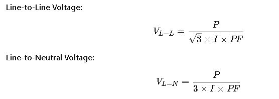
Where:

These formulas are crucial for designing and analyzing industrial power systems.
Common Conversion Values
To facilitate quick calculations, here are some standard conversion values for various power levels:
DC Circuit (Assuming Power Factor = 1)
| Power (W) | Current (A) | Voltage (V) |
|---|---|---|
| 10 | 1 | 10 |
| 50 | 5 | 10 |
| 100 | 10 | 10 |
| 500 | 50 | 10 |
| 1000 | 100 | 10 |
AC Single-Phase Circuit (Assuming PF = 0.9)
| Power (W) | Current (A) | Voltage (V) |
|---|---|---|
| 100 | 1 | 111.11 |
| 500 | 5 | 111.11 |
| 1000 | 10 | 111.11 |
| 2000 | 20 | 111.11 |
AC Three-Phase Circuit (Line-to-Line, PF = 0.9)
| Power (W) | Current (A) | Voltage (V) |
|---|---|---|
| 1000 | 5 | 138.56 |
| 5000 | 25 | 138.56 |
| 10000 | 50 | 138.56 |
These tables provide a quick reference for common power levels, aiding in the design and analysis of electrical systems.
Detailed Explanation of Variables
Understanding each variable in the conversion formulas is essential:
- Power (P): Measured in watts (W), it represents the rate at which energy is consumed or produced in a circuit. It’s calculated as: P=V×I
- Voltage (V): Measured in volts (V), it represents the electrical potential difference between two points. It’s the driving force that pushes electric charges through a conductor.
- Current (I): Measured in amperes (A), it represents the flow of electric charge through a conductor. It’s calculated as:

- Power Factor (PF): A dimensionless number between 0 and 1, it represents the fraction of total power that is used effectively in an AC circuit. A PF of 1 indicates all the power is used effectively, while lower values indicate inefficiencies.
Real-World Applications
1. Residential Solar Power System
Consider a residential solar power system designed to supply 5,000 watts of power. Assuming the system operates at 240 volts and the inverter has a power factor of 0.9, the required current can be calculated as:

This calculation ensures that the wiring and components are appropriately sized to handle the expected current, preventing overheating and potential failures.
2. Industrial Motor Drive
In an industrial setting, a three-phase motor drive requires 15,000 watts of power. Assuming a line-to-line voltage of 400 volts and a power factor of 0.85, the current per phase can be calculated as:

This calculation helps in selecting appropriate circuit breakers and ensuring the motor operates efficiently within its rated capacity.
Additional Considerations
- Impedance in AC Circuits: In AC circuits, especially at high frequencies, impedance (Z) plays a crucial role. The relationship between power, voltage, and impedance is given by:
 This formula is particularly useful in radio frequency (RF) applications and microwave engineering.
 - Safety Margins: When designing electrical systems, it’s essential to include safety margins. For instance, circuits are often designed to handle 125% of the expected load to accommodate unexpected surges and prevent overloads.
- Regulatory Standards: Adhering to local electrical codes and standards, such as the National Electrical Code (NEC) in the United States or the International Electrotechnical Commission (IEC) standards, ensures safety and compliance in electrical installations.
 This formula is particularly useful in radio frequency (RF) applications and microwave engineering.
Further Reading and Resources
For more detailed information on electrical calculations and standards, consider exploring the following resources:
- National Electrical Code (NEC)
- International Electrotechnical Commission (IEC)
- Ohm’s Law and Electrical Calculations
These resources provide comprehensive guidelines and standards for electrical design and safety.