Understanding volts and watts is crucial for electrical engineering, energy management, and efficient system design. This guide explores converting volts to watts, including practical applications, technical considerations, and optimization strategies.
🔄 Need the reverse calculation? If you need to convert from WATTS to VOLT (the opposite direction of this page), use our dedicated WATTS to VOLT calculator with full conversion tables, step-by-step examples, and engineering formulas.
Power, Voltage, and Current Calculator
Conversion Formulas and Their Variables
The conversion from volts (V) to watts (W) depends on the type of electrical system—direct current (DC) or alternating current (AC). Below are the primary formulas used:
1. DC Circuit (Direct Current)
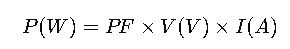
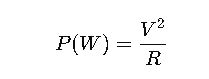
For DC systems, the power in watts is calculated as:

- P(W): Power in watts
- V(V): Voltage in volts
- I(A): Current in amperes (amps)
This formula assumes a power factor of 1, which is typical for DC circuits.
2. AC Single-Phase Circuit
In single-phase AC systems, the power is:
- PF: Power factor (dimensionless, typically between 0 and 1)
- V(V): Voltage in volts (RMS value)
- I(A): Current in amperes (RMS value)
The power factor accounts for the phase difference between voltage and current.
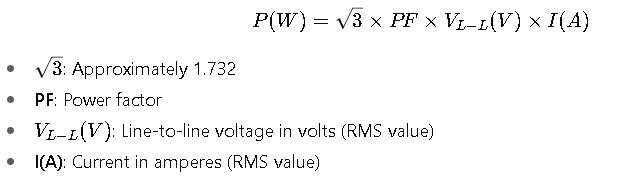
3. AC Three-Phase Circuit (Line-to-Line Voltage)
For three-phase AC systems with line-to-line voltage:
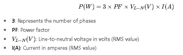
4. AC Three-Phase Circuit (Line-to-Neutral Voltage)
For three-phase AC systems with line-to-neutral voltage:
Common Conversion Values
Below is a table illustrating common voltage and current combinations, along with their corresponding power in watts:
| Voltage (V) | Current (A) | Power (W) |
|---|---|---|
| 12 | 1 | 12 |
| 12 | 5 | 60 |
| 12 | 10 | 120 |
| 12 | 15 | 180 |
| 24 | 1 | 24 |
| 24 | 5 | 120 |
| 24 | 10 | 240 |
| 24 | 15 | 360 |
| 110 | 1 | 110 |
| 110 | 5 | 550 |
| 110 | 10 | 1100 |
| 220 | 1 | 220 |
| 220 | 5 | 1100 |
| 220 | 10 | 2200 |
| 220 | 15 | 3300 |
| 220 | 30 | 6600 |
| 240 | 1 | 240 |
| 240 | 5 | 1200 |
| 240 | 10 | 2400 |
| 240 | 15 | 3600 |
These values are essential for quick reference in various applications, from household wiring to industrial equipment.
Real-World Applications
1. Residential Circuit Design
In residential settings, understanding the power requirements of appliances is crucial for safe and efficient circuit design. For instance, a typical 15-amp circuit at 120 volts can handle up to 1,800 watts. However, to prevent overloading and ensure safety, it’s recommended to use only up to 80% of the circuit’s capacity, equating to 1,440 watts.
2. Industrial Motor Sizing
In industrial applications, accurately calculating the power requirements of motors is vital for selecting appropriately sized equipment. For example, a motor operating at 480 volts with a current draw of 10 amps and a power factor of 0.9 would have a power consumption of:
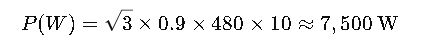
This calculation ensures that the motor is adequately powered without overloading the system.
Advanced Considerations
Power Factor (PF)
The power factor is a critical component in AC circuits, representing the cosine of the phase angle between voltage and current. It indicates the efficiency with which the current is being converted into useful work. A power factor of 1 signifies that all the energy supplied by the source is being used effectively, while values less than 1 indicate inefficiencies.
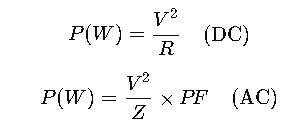
Impedance and Resistance
In DC circuits, Ohm’s Law (V=IR) can be used to determine the current if the resistance is known. Additionally, the power can be calculated using:
In AC circuits, impedance (Z) replaces resistance, and the formulas adjust accordingly.
Extensive Tables for Common Volt-to-Watt Conversions
To enhance usability and practical application, the following table provides a broad set of typical voltage and current combinations, including DC and AC systems with varying power factors. This allows engineers and technicians to quickly reference wattage without performing manual calculations.
DC Circuits (Power Factor = 1)
| Voltage (V) | Current (A) | Power (W) |
|---|---|---|
| 6 | 1 | 6 |
| 6 | 2 | 12 |
| 6 | 5 | 30 |
| 12 | 1 | 12 |
| 12 | 2 | 24 |
| 12 | 5 | 60 |
| 24 | 1 | 24 |
| 24 | 5 | 120 |
| 48 | 1 | 48 |
| 48 | 5 | 240 |
| 48 | 10 | 480 |
| 120 | 1 | 120 |
| 120 | 5 | 600 |
| 120 | 10 | 1,200 |
| 240 | 1 | 240 |
| 240 | 5 | 1,200 |
| 240 | 10 | 2,400 |
Single-Phase AC Circuits (Power Factor 0.8)
| Voltage (V) | Current (A) | PF | Power (W) |
|---|---|---|---|
| 110 | 1 | 0.8 | 88 |
| 110 | 5 | 0.8 | 440 |
| 220 | 1 | 0.8 | 176 |
| 220 | 5 | 0.8 | 880 |
| 220 | 10 | 0.8 | 1,760 |
| 240 | 1 | 0.8 | 192 |
| 240 | 5 | 0.8 | 960 |
| 240 | 10 | 0.8 | 1,920 |
Three-Phase AC Circuits (Power Factor 0.9)
| Line-to-Line Voltage (V) | Current (A) | PF | Power (W) |
|---|---|---|---|
| 208 | 1 | 0.9 | 324 |
| 208 | 5 | 0.9 | 1,620 |
| 208 | 10 | 0.9 | 3,240 |
| 480 | 1 | 0.9 | 748 |
| 480 | 5 | 0.9 | 3,740 |
| 480 | 10 | 0.9 | 7,480 |
| 600 | 1 | 0.9 | 936 |
| 600 | 5 | 0.9 | 4,680 |
| 600 | 10 | 0.9 | 9,360 |
Detailed Explanation of Variables
Voltage (V)
Voltage represents the potential difference between two points in a circuit. Typical household voltages include 110–120 V (North America) and 220–240 V (Europe, Asia). Industrial systems often use higher voltages such as 480 V, 600 V, or 690 V three-phase.
Current (I)
Current is the flow of electric charge, measured in amperes. Household circuits usually range from 1 A to 30 A, while industrial motors may draw hundreds of amperes.
Power Factor (PF)
In AC systems, PF accounts for the phase shift between voltage and current:
- PF = 1: Purely resistive load, all energy is converted to work.
- PF < 1: Some energy is reactive, as in motors or inductive loads.
Typical values: 0.8 (motors, lighting), 0.95 (well-designed industrial loads).
Resistance (R) and Impedance (Z)
For DC, R represents opposition to current flow: V=I×R
For AC, Z includes resistance and reactance: V=I×Z
Power can also be expressed as:
Real-World Examples
Example 1: Designing a Residential Lighting Circuit
A living room requires lighting for 10 LED bulbs rated at 12 W each. The voltage is 120 V DC:
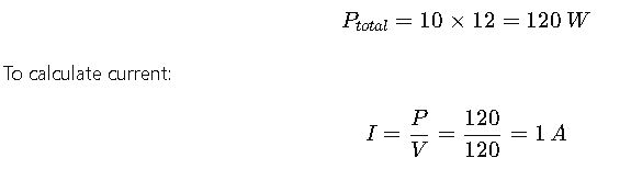
A 120 V, 15 A circuit is sufficient with a safety margin.
Example 2: Industrial Motor Load
An industrial motor operates on a 480 V three-phase system, drawing 15 A with PF 0.9:
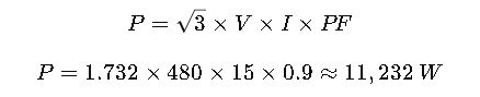
This calculation helps select correct circuit breakers and ensures safe operation.
Practical Volt-to-Watt Conversion Tables for Professionals
Engineers and electricians frequently need quick reference tables to determine power consumption without performing calculations. The tables below illustrate typical voltage-to-watt relationships across residential, commercial, and industrial systems.
Common Household Volt-to-Watt Values
| Voltage (V) | Appliance/Load | Typical Power (W) |
|---|---|---|
| 120 | LED Lamp | 10–20 |
| 120 | Laptop Charger | 60–100 |
| 120 | Microwave | 800–1,200 |
| 120 | Refrigerator | 100–800 |
| 240 | Air Conditioner | 1,000–3,500 |
| 240 | Electric Oven | 2,000–5,000 |
| 240 | Water Heater | 3,000–4,500 |
Industrial and Commercial Loads
| Voltage (V) | Equipment | Power Range (W) |
|---|---|---|
| 208 | Commercial Lighting | 50–500 |
| 208 | HVAC Units | 2,000–10,000 |
| 480 | Motors | 5,000–50,000 |
| 600 | Pumps | 10,000–100,000 |
| 600 | Conveyor Systems | 15,000–75,000 |
These tables are essential tools for load planning, energy audits, and ensuring that circuits are not overloaded.
Real-World Applications Without Formulas
1. Residential Lighting and Appliance Planning
In residential construction, understanding power consumption is crucial for selecting circuit breakers, wire gauges, and energy-efficient devices. For example, a household with multiple high-power appliances, such as microwaves and air conditioners, needs circuits rated to handle combined wattage safely. Using tables and typical wattage values, engineers can plan the electrical distribution to avoid overloading and maintain safety standards.
Energy-efficient lighting, such as LED technology, has dramatically reduced household power consumption. By referencing wattage tables, designers can estimate the total load for a room and optimize breaker sizing and wiring, reducing installation cost and energy waste.
2. Industrial Machinery Load Management
In industrial environments, motors, pumps, and large HVAC systems are primary power consumers. Knowing the typical wattage for various equipment types allows engineers to:
- Size transformers and distribution panels correctly
- Implement energy management systems
- Reduce operational downtime by preventing overloads
For instance, a factory with multiple three-phase motors must ensure that the total wattage does not exceed the transformer capacity. Tables that list typical voltage-to-wattage relationships help engineers make these decisions efficiently without performing repetitive calculations.
3. Data Centers and IT Infrastructure
Data centers demand precise energy planning. Servers, cooling units, and networking equipment have specific power requirements. Engineers rely on conversion tables to estimate total consumption and optimize UPS systems. Using standard wattage values, operators can ensure backup generators and battery systems are properly sized to handle peak loads.
Practical Considerations for Engineers
Even without calculations, understanding the principles behind volts and watts helps in:
- Energy efficiency planning: Selecting devices and motors with lower wattage consumption reduces energy bills.
- Circuit safety: Avoiding overloading by referencing expected wattage ensures compliance with electrical codes.
- Load balancing: Distributing electrical loads evenly across phases in industrial systems prevents overheating.
- Preventive maintenance: Recognizing typical power consumption helps detect unusual energy spikes that may indicate equipment malfunction.
Power Factor Awareness in AC Systems
While formulas are excluded, it’s important to understand power factor conceptually:
- AC devices like motors, fluorescent lighting, and transformers do not consume all supplied energy efficiently.
- A lower power factor means that more current is drawn for the same power output, affecting conductor sizing and energy efficiency.
- Engineers use wattage tables and typical power factor values to anticipate real-world energy consumption.
Extended Tables for Professional Reference
Medium-Voltage Equipment (Commercial and Industrial)
| Voltage (V) | Equipment Type | Typical Wattage Range |
|---|---|---|
| 208 | Lighting Systems | 50–500 W |
| 208 | Small Motors | 500–5,000 W |
| 480 | Pumps | 5,000–50,000 W |
| 480 | Fans | 1,000–15,000 W |
| 600 | Conveyor Belts | 15,000–75,000 W |
| 600 | Compressors | 20,000–100,000 W |
High-Voltage Industrial Machinery
| Voltage (V) | Equipment Type | Typical Wattage Range |
|---|---|---|
| 1,000 | Heavy Duty Motors | 50,000–500,000 W |
| 1,000 | Industrial Furnaces | 100,000–1,000,000 W |
| 1,500 | Steel Manufacturing | 250,000–2,000,000 W |
| 3,000 | High Power Transformers | 500,000–5,000,000 W |
These tables are especially useful for engineers designing energy distribution in large-scale industrial or commercial facilities.