In three-phase systems, mastering phase-neutral and phase-phase voltage conversion ensures precise engineering, system compatibility, and safety.
This technical guide explores formulas, conversion methods, and real-world applications, providing engineers comprehensive tools for accurate calculations.
Line-to-Neutral ↔ Line-to-Line Voltage Calculator
Convert VL-N ↔ VL-L for three-phase (√3) or split-phase (×2). Fast, accurate, SEO-ready.
How do I convert L-N to L-L in three-phase?
How do I convert L-L to L-N in three-phase?
When do I use ×2 instead of √3?
Common nominal sets
Rounding & tolerance
Voltage Conversion Formulas
1. Phase-Neutral to Phase-Phase Voltage
In a balanced three-phase system, the phase-phase voltage (VLL) is related to the phase-neutral voltage (VLN) by the following formula:
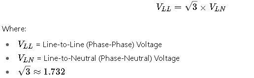
This relationship arises due to the 120° phase separation between the three phases in a balanced system.
2. Phase-Phase to Phase-Neutral Voltage
Conversely, to determine the phase-neutral voltage from the phase-phase voltage:
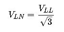
This formula is essential when converting between different voltage levels in various parts of an electrical system.
Common Voltage Values in Three-Phase Systems
Below is a table showcasing typical phase-neutral and phase-phase voltage values across various systems:
| System Type | Phase-Neutral Voltage (V) | Phase-Phase Voltage (V) |
|---|---|---|
| Low Voltage (LV) | 230 | 400 |
| Medium Voltage (MV) | 400 | 690 |
| High Voltage (HV) | 690 | 1,200 |
| Industrial Systems | 277 | 480 |
| Commercial Systems | 120 | 208 |
These values align with international standards, ensuring compatibility and safety across different regions and applications.
Detailed Explanation of Variables
- Phase-Neutral Voltage (VLN): The voltage measured between any phase conductor and the neutral point. It is the voltage available for single-phase loads in a three-phase system.
- Phase-Phase Voltage (VLL): The voltage measured between any two phase conductors. This voltage is typically higher than the phase-neutral voltage and is used for three-phase loads.
 : The square root of three, approximately 1.732, is a constant that arises from the geometry of a balanced three-phase system. It accounts for the 120° phase separation between the phases.
Understanding these variables and their relationships is fundamental for designing and analyzing three-phase electrical systems.
Practical Examples
Example 1: Industrial Motor Voltage Compatibility
An industrial facility operates a motor rated for 230 V phase-neutral voltage. The available supply is 400 V phase-phase. To ensure compatibility:
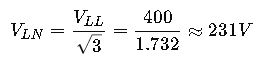
This calculation confirms that the supply voltage is suitable for the motor, ensuring efficient operation and longevity.
Example 2: Commercial Building Lighting System
A commercial building’s lighting system is designed for 277 V phase-neutral voltage. The supply voltage is 480 V phase-phase. To verify compatibility:
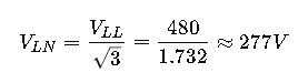
This result indicates that the supply voltage aligns with the system’s requirements, promoting energy efficiency and reducing the risk of equipment damage.
Advanced Considerations
1. Voltage Imbalance
In real-world systems, voltage imbalances can occur due to uneven load distribution or faults. These imbalances can affect the performance of equipment and lead to overheating or reduced efficiency. Monitoring and correcting voltage imbalances is essential for maintaining system stability.
2. Harmonics and Power Quality
Harmonics, caused by non-linear loads, can distort the voltage waveform, leading to potential issues in equipment performance. Implementing filters and using power quality analyzers can help mitigate these effects.
3. System Configuration
The method of voltage measurement can vary based on system configuration:
- Star (Wye) Configuration: The phase-neutral voltage is equal to the line-to-neutral voltage, and the phase-phase voltage is related to the phase-neutral voltage by the 3\sqrt{3}3 factor.
- Delta Configuration: The phase-phase voltage is equal to the phase-neutral voltage, and the phase-neutral voltage is related to the phase-phase voltage by the 13\frac{1}{\sqrt{3}}31 factor.
Understanding the system configuration is crucial for accurate voltage measurements and conversions.
Extended Conversion Tables for Phase-Neutral to Phase-Phase Voltages
Table 1: Common International Standard Voltages (IEC 60038 Reference)
| Phase-Neutral Voltage (V) | Phase-Phase Voltage (V) | Application Region/Use Case |
|---|---|---|
| 120 | 208 | North America – Commercial Buildings |
| 127 | 220 | Latin America – Residential Systems |
| 133 | 230 | Legacy US Systems |
| 220 | 380 | Europe, Asia – Industrial |
| 230 | 400 | Europe (IEC Standard) |
| 240 | 415 | UK, Australia – Residential/Industrial |
| 277 | 480 | North America – Lighting Circuits |
| 346 | 600 | North America – Industrial Distribution |
| 400 | 690 | Heavy Industry (Mining, Marine, Steel) |
| 600 | 1,039 | Special Industrial Systems |
| 1,000 | 1,732 | High Voltage Distribution |
Table 2: Detailed Conversion (Step Values)
This table helps visualize conversions in smaller increments for common engineering calculations:
| Phase-Neutral Voltage (V) | Phase-Phase Voltage (V) |
|---|---|
| 100 | 173 |
| 110 | 190 |
| 115 | 199 |
| 120 | 208 |
| 127 | 220 |
| 130 | 225 |
| 133 | 230 |
| 200 | 346 |
| 208 | 360 |
| 220 | 381 |
| 230 | 400 |
| 240 | 415 |
| 250 | 433 |
| 277 | 480 |
| 300 | 520 |
| 346 | 600 |
| 400 | 693 |
| 500 | 866 |
| 600 | 1,039 |
| 690 | 1,195 |
| 1,000 | 1,732 |
Table 3: Backward Conversion (Phase-Phase to Phase-Neutral)
| Phase-Phase Voltage (V) | Phase-Neutral Voltage (V) | Example Application |
|---|---|---|
| 208 | 120 | US Commercial Buildings |
| 220 | 127 | Latin America Residential |
| 230 | 133 | Old Distribution Systems |
| 380 | 220 | IEC Industrial Systems |
| 400 | 230 | European Standard |
| 415 | 240 | UK, Australia |
| 480 | 277 | US Lighting |
| 600 | 346 | Heavy Industry |
| 690 | 400 | Steel Mills, Mines |
| 1,039 | 600 | Large Industrial Distribution |
| 1,732 | 1,000 | High Voltage Systems |
Table 4: Quick Engineering Reference – Approximate Multiples
| Phase-Neutral Voltage (V) | ×√3 | Result (Line-Line) V |
|---|---|---|
| 100 | 1.732 | 173 |
| 200 | 1.732 | 346 |
| 300 | 1.732 | 520 |
| 400 | 1.732 | 693 |
| 500 | 1.732 | 866 |
| 600 | 1.732 | 1,039 |
| 700 | 1.732 | 1,212 |
| 800 | 1.732 | 1,386 |
| 900 | 1.732 | 1,559 |
| 1,000 | 1.732 | 1,732 |