The conversion between square millimeters and American Wire Gauge is essential in engineering, manufacturing, and power systems.
Globally, engineers must match metric cable sizes with AWG standards; this guide offers formulas, tables, and examples.
mm² to AWG Converter (Wire Gauge)
How do we convert mm² to AWG?
What does “next larger (safer)” mean?
Solid vs stranded?
Why mm² to AWG Conversion Matters
- International projects: Engineers working across different countries need to specify cable sizes that comply with local standards.
- Equipment imports: Many machines are designed in AWG but installed in countries using mm².
- Electrical safety compliance: Correct sizing prevents overheating, voltage drop issues, and potential fire hazards.
- Compatibility: Matching wire sizes ensures correct fit into terminals, connectors, and protective devices.
For electrical design to be safe and efficient, engineers must understand not just the conversion values, but also the current-carrying capacity and mechanical properties associated with each size.
Extended mm² to AWG Conversion Table
Below is a professional-grade, extended conversion chart including common and intermediate sizes, covering the range from 0.05 mm² (used in electronics) to 500 mm² (used in high-power distribution).
Table 1 – Metric to AWG Conversion (Nominal Values)
| mm² (Cross-Sectional Area) | AWG Size | Diameter (mm) | Diameter (inches) | Typical Current Capacity (A) | Common Applications |
|---|---|---|---|---|---|
| 0.05 mm² | 30 AWG | 0.255 | 0.0100 | 0.5 – 0.9 | Signal wiring in electronics |
| 0.08 mm² | 28 AWG | 0.321 | 0.0126 | 0.8 – 1.4 | Low-current sensors |
| 0.13 mm² | 26 AWG | 0.405 | 0.0159 | 1.0 – 2.2 | Data cables, small control wiring |
| 0.20 mm² | 24 AWG | 0.511 | 0.0201 | 2 – 3.5 | Ethernet, control circuits |
| 0.33 mm² | 22 AWG | 0.644 | 0.0253 | 3 – 7 | Alarm systems, signal wiring |
| 0.52 mm² | 20 AWG | 0.812 | 0.0320 | 5 – 11 | Small power circuits |
| 0.823 mm² | 18 AWG | 1.024 | 0.0403 | 7 – 16 | Lighting control, small loads |
| 1.31 mm² | 16 AWG | 1.291 | 0.0508 | 10 – 22 | Industrial control panels |
| 2.08 mm² | 14 AWG | 1.628 | 0.0641 | 15 – 32 | Domestic wiring in USA |
| 3.31 mm² | 12 AWG | 2.053 | 0.0808 | 20 – 41 | Power circuits |
| 5.26 mm² | 10 AWG | 2.588 | 0.1019 | 30 – 55 | Industrial machinery |
| 8.37 mm² | 8 AWG | 3.264 | 0.1285 | 40 – 73 | Subpanels, large motors |
| 13.3 mm² | 6 AWG | 4.115 | 0.1620 | 55 – 101 | Feeders, welding cables |
| 21.1 mm² | 4 AWG | 5.189 | 0.2043 | 70 – 135 | Main service feeders |
| 33.6 mm² | 2 AWG | 6.544 | 0.2576 | 95 – 181 | Industrial feeders |
| 53.5 mm² | 1/0 AWG | 8.251 | 0.3248 | 150 – 245 | High-power feeders |
| 85.0 mm² | 3/0 AWG | 10.404 | 0.4096 | 225 – 330 | Large service entrances |
| 107.2 mm² | 4/0 AWG | 11.684 | 0.4600 | 260 – 405 | Utility connections |
| 120 mm² | 250 kcmil | 13.510 | 0.5318 | 290 – 430 | Power distribution |
| 150 mm² | 300 kcmil | 14.732 | 0.5800 | 320 – 480 | Industrial feeders |
| 185 mm² | 350 kcmil | 15.875 | 0.6250 | 350 – 520 | Large commercial feeders |
| 240 mm² | 500 kcmil | 18.796 | 0.7400 | 430 – 650 | Heavy industrial power |
| 300 mm² | 600 kcmil | 20.930 | 0.8240 | 500 – 750 | Substation feeders |
| 400 mm² | 800 kcmil | 23.800 | 0.9370 | 630 – 900 | Utility transmission |
| 500 mm² | 1000 kcmil | 27.050 | 1.0650 | 750 – 1130 | High-capacity power lines |
Note: Current capacity values are approximate and depend on installation conditions, insulation type, ambient temperature, and applicable standards such as IEC 60364 or NEC (NFPA 70).
For more detailed ampacity charts, consult:
Formulas for mm² to AWG Conversion
The AWG system is logarithmic, meaning each step in gauge size corresponds to a constant factor in diameter change.
The standard mathematical relationship between AWG and diameter (inches) is:
Where:
1. AWG to mm² Formula
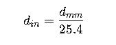
- Convert AWG to diameter (inches):
- Convert inches to millimeters:
- Calculate cross-sectional area:
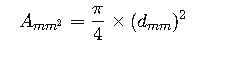
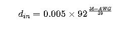
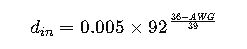
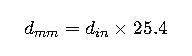
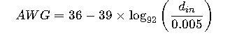
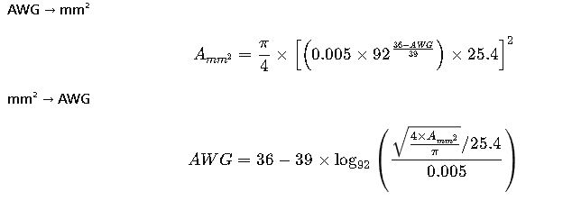
2. mm² to AWG Formula
- Calculate diameter in mm:
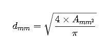
- Convert mm to inches:
- Invert the AWG equation:
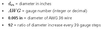
Variables Explanation
- AWG: American Wire Gauge number
- A_{mm²}: Cross-sectional area in square millimeters
- d_{mm}: Wire diameter in millimeters
- d_{in}: Wire diameter in inches
- π: Mathematical constant (~3.1416)
- 92: Scaling factor of AWG system
- 0.005 in: Diameter of AWG 36 wire
Real-World Application Examples of mm² to AWG Conversion
Example 1 – International Machine Installation
Scenario:
A U.S.-manufactured industrial packaging machine is being installed in Germany. The machine’s wiring diagram specifies 12 AWG copper conductors for the main control circuits. The German installer must choose an equivalent size in mm² to comply with local cable suppliers and IEC standards.
Step-by-Step Conversion:
1.Identify the AWG size:
The diagram specifies 12 AWG.
2.Find the equivalent mm² from the conversion formula:
Step 1: Diameter in inches:
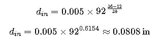
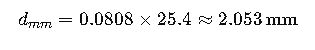
Step 2: Diameter in mm:
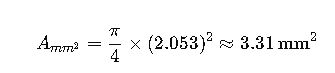
Step 3: Area in mm²:
3.Result:
12 AWG ≈ 3.31 mm².
In practice, the nearest standard size available in Germany is 4 mm², which slightly exceeds the AWG 12 capacity, ensuring safety.
Application Note:
When replacing AWG sizes with mm² in international projects, always choose the next higher metric size to account for manufacturing tolerances and compliance with IEC 60364.
Example 2 – Solar PV System Upgrade
Scenario:
A solar installation in California needs to upgrade from 10 AWG cables to metric equivalents because the client sources cables from a European supplier. The cable run length is 30 meters, carrying 40 A DC at 600 V.
Step-by-Step Conversion:
1.Identify the existing AWG:
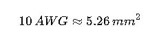
10 AWG.
2.Convert AWG to mm²:
From the extended table:
3.Check ampacity:
NEC Table 310.16 (75°C copper, THWN insulation) gives 10 AWG = 40 A.
IEC 60364-5-52 allows 6 mm² cable for 40 A DC in free air.
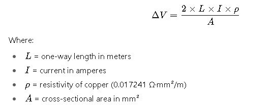
4.Adjust for voltage drop:
Voltage drop formula:
Calculation:
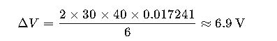
This is about 1.15% of 600 V, well within the 3% limit for DC systems.
- Result:
Replace 10 AWG with 6 mm² cable, ensuring compliance with both NEC and IEC voltage drop recommendations.
Technical Considerations When Converting mm² to AWG
1. Tolerance and Manufacturing Variations
AWG and mm² are nominal sizes. Real wire diameters can vary due to:
- Stranding: Flexible cables have slightly larger overall diameters for the same cross-section.
- Insulation thickness: Affects fit into lugs/connectors.
- Production tolerances: ±5% variance is common.
2. Material Conductivity
- Standard tables assume 99.9% pure copper.
- Aluminum conductors require larger sizes for equivalent ampacity (approximately +2 AWG sizes or +60% cross-section).
3. Insulation Type
Current-carrying capacity depends heavily on insulation material:
- PVC (75°C rating)
- XLPE (90°C rating)
- Teflon/PTFE (200°C rating)
4. Application Environment
Factors such as ambient temperature, bundling, and installation method reduce ampacity, requiring up-sizing.
5. Compliance with Standards
Two main families of standards affect sizing:
- NEC (NFPA 70) – United States
- IEC 60364 – International
Always use the stricter requirement when crossing between systems.
Quick Reference Formula Recap
Authoritative Resources
For deeper technical validation and compliance checks: