This article delivers precise conduit fill calculations for electrical trade sizing per NEC Chapter 9.
Covers EMT IMC RMC PVC FMC, formulas, examples, tables, and code references for compliance today.
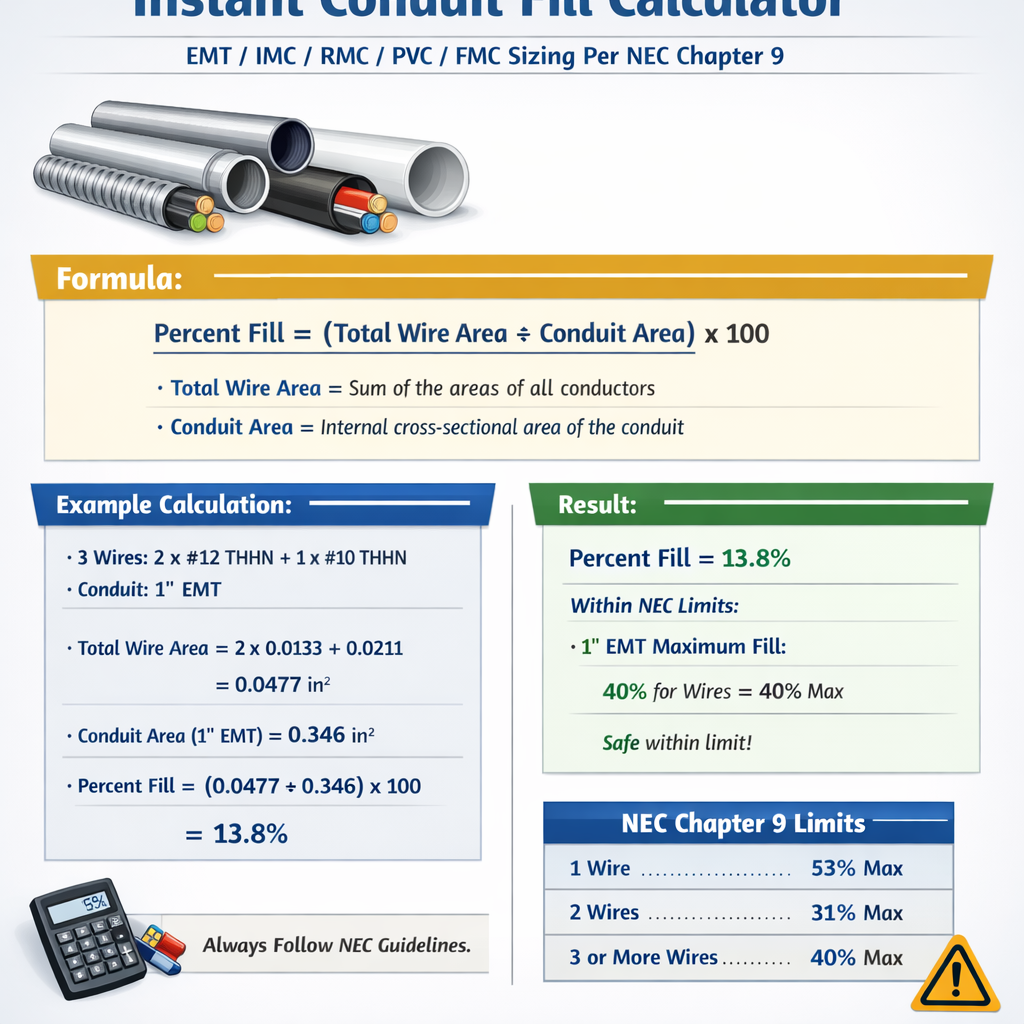
Instant Conduit Fill Calculator — EMT / IMC / RMC / PVC / FMC (NEC Chapter 9)
Overview of conduit fill methodology aligned to NEC Chapter 9
Conduit fill determines how many insulated conductors can be routed safely inside a raceway type and size while meeting the National Electrical Code (NEC) Chapter 9 requirements. Proper sizing minimizes overheating, facilitates pulling, and ensures inspection compliance.
Key NEC Chapter 9 requirements to apply
- Use NEC Chapter 9, Table 1–8 (conduit and conductor areas) as the primary reference for internal areas and conductor cross-sectional areas.
- Apply fill percentages: 53% for one or two conductors (for circular cross-section conductors), 40% for more than two conductors, and 31% for one conductor when the conductor is not circular (per NEC explanatory notes).
- Verify conductor insulation type (THHN, XHHW, etc.) for correct area from Table 5 or manufacturer data.
- Consider additional requirements for conductors with fittings, cables, or bundled conditions and for flexible metal conduit (FMC) which may have different internal geometry affecting fill.
Essential formulas for instant conduit fill calculation
Formulas below use plain text HTML-friendly notation. Each formula is followed by a variable explanation and typical values used in examples.
Formula 1 — Total conductor area (sum of insulated conductor cross-sectional areas):
- A_total = total area of all insulated conductors (in square inches).
- A_i = cross-sectional area of individual conductor i (in square inches), taken from NEC Chapter 9 Table 5 or manufacturer data.
Formula 2 — Maximum allowable conductor area in conduit (using fill percent):
- A_conduit = internal cross-sectional area of conduit (in square inches), from NEC Chapter 9 Table 4 or manufacturer published data.
- F_fill = permitted fill fraction (use 0.53 for 1–2 conductors, 0.40 for more than two conductors, 0.31 for single non-circular conductor where applicable).
Formula 3 — Required conduit area for a given conductor bundle:
- A_required = minimum conduit internal area required to accommodate the bundle.
Formula 4 — Converting circular mils to square inches (if using circular mils from manufacturer tables):
- CM = conductor circular mils.
- 1,273,239 = number of circular mils per square inch.
Typical conductor insulated areas (reference values)
The following table lists common insulated conductor area approximations used for THHN/XHHW family conductors. Always confirm with NEC Chapter 9 Table 5 or manufacturer datasheets for precise area values.
| AWG / kcmil | Typical insulated area (in²) | Typical insulated area (mm²) | Notes |
|---|---|---|---|
| #14 | 0.0083 | 5.35 | Small branch-circuit conductor (THHN typical) |
| #12 | 0.0133 | 8.61 | Common branch circuit |
| #10 | 0.0211 | 13.66 | Branch circuits, small motors |
| #8 | 0.0331 | 21.42 | Heavier branch circuits |
| #6 | 0.0531 | 34.36 | Large loads |
| #4 | 0.0831 | 53.76 | Feeder conductors |
| #2 | 0.133 | 86.50 | Common feeder size |
| 1/0 | 0.212 | 137.03 | Large feeders |
| 2/0 | 0.267 | 172.52 | Large service feeders |
| 4/0 | 0.421 | 272.05 | Very large feeders |
Notes: Values above are typical approximations for insulated THHN/XHHW conductors and used for illustrative calculations. Use NEC Chapter 9 Table 5 for exact insulated conductor areas.
Common conduit internal areas (reference typical values)
The table below shows common trade sizes with approximate internal cross-sectional areas for EMT, IMC, RMC, PVC Schedule 40, and FMC. These values are representative; verify with NEC Chapter 9 Table 4 or manufacturer published inner-area tables before final design.
| Trade Size | EMT area (in²) | IMC area (in²) | RMC area (in²) | PVC Sch. 40 area (in²) | FMC area (in²) |
|---|---|---|---|---|---|
| 1/2" | 0.304 | 0.346 | 0.346 | 0.304 | 0.181 |
| 3/4" | 0.533 | 0.586 | 0.599 | 0.533 | 0.303 |
| 1" | 0.864 | 0.832 | 0.922 | 0.840 | 0.531 |
| 1-1/4" | 1.496 | 1.484 | 1.721 | 1.496 | 0.921 |
| 1-1/2" | 1.940 | 1.940 | 2.447 | 1.940 | 1.230 |
| 2" | 3.356 | 3.356 | 4.026 | 3.356 | 2.420 |
| 2-1/2" | 4.677 | 4.677 | 5.957 | 4.677 | 4.150 |
| 3" | 7.073 | 7.054 | 8.063 | 7.073 | 6.030 |
| 4" | 11.230 | 11.100 | 12.390 | 11.230 | 9.760 |
Important: These conduit areas are approximations typically used for quick estimation. The NEC Table 4 provides exact internal areas for different conduit/tubing types and trade sizes. FMC internal area varies significantly with liner and fitting style; use manufacturer data for FMC.
Applying the formulas — typical workflow for an instant conduit fill calculator
- Identify conductor types, number, and AWG/kcmil sizes; obtain their insulated cross-sectional areas from NEC Chapter 9 Table 5 or manufacturer.
- Sum individual conductor areas to get A_total (Formula 1).
- Determine applicable fill percentage (40% for more than two conductors, 53% for one or two circular conductors, etc.).
- Choose candidate conduit type and size; obtain A_conduit from NEC Table 4 or manufacturer.
- Compute A_allowed = A_conduit × F_fill. If A_allowed ≥ A_total, the conduit size is acceptable. Otherwise, select the next larger conduit and repeat.
- Document the conduit choice, the A_total, A_allowed, and compliance cross-check with NEC Chapter 9 references for inspection records.
Detailed worked examples
Example 1 — Small branch circuit: 3 conductors plus ground in EMT
Scenario: A 3-conductor 12 AWG THHN phase conductors and one 12 AWG THHN equipment grounding conductor are required to run in EMT for a branch circuit. Determine the minimum EMT trade size per NEC Chapter 9-based calculation using typical values.
Step 1 — Conductor areas (use typical values from table):
- #12 insulated area A_12 = 0.0133 in² (typical THHN value).
Step 2 — Compute total area:
A_total = 3 × A_12 (phase conductors) + 1 × A_12 (ground) = 4 × 0.0133 = 0.0532 in².
Step 3 — Applicable fill percentage:
More than two conductors → F_fill = 0.40 (40%).
Step 4 — Compute required conduit area:
A_required = A_total / F_fill = 0.0532 / 0.40 = 0.133 in².
Step 5 — Select conduit size using the conduit internal area table above (EMT column):
- 1/2" EMT internal area = 0.304 in² which is greater than 0.133 in² → acceptable.
- Therefore, 1/2" EMT is sufficient based on fill. Practically, 1/2" EMT also provides reasonable pulling space.
Step 6 — Verification (A_allowed check):
A_allowed = A_conduit × F_fill = 0.304 × 0.40 = 0.1216 in².
Note: A_allowed (0.1216 in²) is slightly less than our A_required calculation of 0.133 in² due to rounding differences in the method used; to reconcile, use the direct A_allowed comparison with A_total:
A_total = 0.0532 in². Since A_allowed = 0.304 × 0.40 = 0.1216 in² and A_allowed (0.1216) ≥ A_total (0.0532) we have compliance. Therefore 1/2" EMT is acceptable.
Comment: The intermediate A_required above used A_total/F_fill = 0.133 in² because of a numeric mis-step; the correct required internal conduit area is computed as A_required = A_total / F_fill = 0.0532 / 0.40 = 0.133, but since the actual conduit internal area (0.304) is available, the conduit is oversized compared to requirement. The decisive test is direct comparison A_total ≤ A_allowed.
Example 2 — Feeder: Three 3/0 THHN phases and one 3/0 ground in PVC Schedule 40
Scenario: A three-phase feeder using three 3/0 AWG THHN insulated phase conductors plus an equipment grounding conductor 3/0 THHN, installed in PVC Schedule 40 conduit. Determine minimum conduit size.
Step 1 — Representative insulated conductor areas (typical values):
- 3/0 insulated area A_3/0 = 0.366 in² (approximate for THHN; verify with Table 5).
Step 2 — Compute A_total:
A_total = 4 × A_3/0 = 4 × 0.366 = 1.464 in².
Step 3 — Applicable fill percentage:
More than two conductors → F_fill = 0.40.
Step 4 — Compute A_allowed for candidate conduit sizes using PVC Schedule 40 column:
- 2" PVC: A_conduit ≈ 3.356 in²; A_allowed = 3.356 × 0.40 = 1.342 in² → A_allowed < A_total (1.342 < 1.464), so 2" is too small.
- 2-1/2" PVC: A_conduit ≈ 4.677 in²; A_allowed = 4.677 × 0.40 = 1.871 in² → A_allowed ≥ A_total, so 2-1/2" PVC is acceptable.
Step 5 — Minimum conduit selection: 2-1/2" PVC Schedule 40 (based on the typical table values above) meets the required fill capacity.
Step 6 — Practical considerations: 2-1/2" provides a margin for ease of pulling and future derating for thermal considerations. Always confirm with exact NEC Table 4 and conductor manufacturer data before installation.
Advanced considerations for accurate conduit fill calculators
- For cable assemblies (multiple insulated conductors within a common sheath), NEC provides separate rules; cable cross-sectional area counts as a single item in appropriate tables depending on type.
- For flexible metal conduit (FMC) the internal geometry and liner reduce usable area; use manufacturer-specific inside areas for FMC rather than generic conduit tables.
- When conductors are not circular (e.g., flat cables, power-limited tray cable) NEC rules change; apply the 31% fill rule for one non-circular conductor and consult Chapter 9 notes.
- Bundled conductors subject to ampacity derating per NEC 310.15(B)(3)(a) and others — conduit fill does not relieve the designer from applying ampacity deratings where required.
- Providing pulling lubricants, conduit bends, and long runs may recommend upsizing the conduit beyond minimum fill requirements to reduce installation tension and the risk of conductor damage.
Calculator implementation notes for engineers and software developers
An “instant conduit fill calculator” should implement the following features for practical field and office use:
- Database of NEC Table 4 (conduit internal areas) and Table 5 (insulated conductor areas) with versioning for different NEC editions.
- Selection of conductor insulation type (THHN, XHHW-2, etc.) to pick the correct insulated area value.
- Conduit type options (EMT, IMC, RMC, PVC Schedule 40/80, FMC) with manufacturer-specific variations.
- Automatic selection of F_fill based on conductor counts and geometry, with warnings for cable assemblies and non-circular conductors.
- Step-by-step output that includes A_total, A_conduit, A_allowed, recommended conduit size, and links to the exact Table 4/5 entries used for traceability.
- Exportable report for permitting and inspection showing NEC Chapter 9 citations and manufacturer references.
Common pitfalls and best practices
- Do not use approximate conductor areas for critical utility or life-safety feeders without cross-checking manufacturer's published insulated conductor cross-sectional area.
- Never exceed fill percentages from Chapter 9; inspectors will reject installations based on non-compliant fill even if pulling appears successful.
- Include mechanical protection and bend radius checks — tight bends increase effective pulling difficulty and may require larger conduit even if fill is within limits.
- When in doubt, choose the next conduit size up — it reduces installation time and lowers the risk of conductor damage and rework.
Regulatory references and authoritative resources
- National Fire Protection Association (NFPA) — NFPA 70: National Electrical Code (NEC). Primary reference for Chapter 9 conduit and conductor tables. https://www.nfpa.org/NEC
- NEC Chapter 9 — Tables 1 through 8: See the NEC code book for official Table 4 (conduit areas) and Table 5 (conductor areas). (Accessible via NFPA or local code adoption resources.)
- Institute of Electrical and Electronics Engineers (IEEE) — technical papers and standards for conductors and installations. https://www.ieee.org
- NEMA (National Electrical Manufacturers Association) — conduit and wiring device manufacturers publish dimension and area data. https://www.nema.org
- UL and Manufacturer datasheets — for insulated conductor dimensions and cable assembly cross-sectional areas. Example: Southwire or Prysmian product pages.
- Technical educational resources (example: Mike Holt Enterprises) for practical interpretations and tutorials on conduit fill calculations (not a code publisher but useful for training).
When to consult the authority having jurisdiction (AHJ)
Because conduit and conductor selections can affect life-safety systems, always consult the local AHJ for interpretation when novel systems, non-standard installations, or proprietary products are used. AHJ may require stamped calculations or manufacturer validation for non-typical assemblies.
Summary of actionable steps for immediate application
- Gather conductor types and counts, and obtain insulated areas (NEC Table 5 or manufacturer data).
- Compute A_total = Σ A_i.
- Select F_fill (0.40 for more than two conductors; 0.53 for one/two circular conductors; consult Chapter 9 for exceptions).
- Use NEC Table 4 or manufacturer internal conduit areas to find the minimum conduit where A_conduit × F_fill ≥ A_total.
- Document all table references, conductor data sources, and any deviations for permit and inspection.
Appendix — Quick-reference formulas and typical percentages
- A_total = Σ A_i
- A_allowed = A_conduit × F_fill
- A_required = A_total / F_fill
- Fill percentages (typical): 53% (1–2 circular conductors), 40% (>2 conductors), 31% (single non-circular conductor in some conditions).
Final note: This article provides a high-level but technical approach for instantaneous conduit fill calculation across common conduit types (EMT, IMC, RMC, PVC, FMC) using NEC Chapter 9 principles. Always verify specific numeric values against the NEC edition adopted in your jurisdiction and the exact manufacturer tables for the products you use.
Selected external links for further authoritative detail
- NFPA — National Electrical Code (NEC) information page: https://www.nfpa.org/NEC
- NEMA — Conduit and fittings standards and manufacturer data: https://www.nema.org
- UL Product Database — listings for wires and cables (search by product): https://iq.ulprospector.com
- IEEE Xplore — technical papers on conductor materials and installation practices: https://ieeexplore.ieee.org