This article explains an instant three-phase panel load balancing calculator for accurate scheduling and planning.
Engineers assign balanced currents quickly, generate schedules, and ensure compliance with electrical standards and safety.
3-Phase Panel Load Balancing Calculator for Phase Currents and Imbalance Assessment
Background and scope for three-phase panel balancing
Three-phase panel load balancing is a critical operational task for electrical distribution systems in commercial and industrial facilities. Accurate balancing minimizes neutral currents, reduces thermal stress on conductors and breakers, improves power quality, and optimizes capacity planning for panel schedules. This article targets engineers, electricians, and facility managers who require an instant, algorithmic assignment helper integrated with a load balancing calculator to produce accurate, code-compliant panel schedules.The content covers theoretical formulas, assignment algorithms, typical engineering values, and two fully worked real-world examples. It summarizes normative references and practical integration tips for automation in scheduling workflows and building management systems.Fundamental objectives and performance metrics
Balancing objectives are typically one or more of the following:- Minimize maximum phase current (minimize I_max)
- Minimize phase current variance or imbalance percentage
- Respect individual circuit constraints (breaker size, conductor ampacity)
- Optimize thermal capacity utilization and defer upgrades
- Absolute imbalance: I_max - I_min (A)
- Relative imbalance: (I_max - I_min) / I_avg × 100 (%)
- Phase utilization: I_phase / Breaker_rating × 100 (%)
- Neutral current estimate: For perfectly balanced three-phase, I_neutral ≈ 0; for unbalanced, I_neutral = |I_A + I_B + I_C| (vector sum)
Calculation methodology and algorithmic strategies
Effective assignment helpers implement combinatorial or heuristic algorithms to allocate single-phase and two-phase loads into three-phase panels. Strategies include:- Greedy sorting by descending current and assigning to the currently lowest phase (fast heuristic)
- Balanced partitioning using dynamic programming for small sets (exact minimal imbalance)
- Integer linear programming (ILP) to minimize a weighted objective such as I_max or variance (best for automated batch assignments)
- Metaheuristics (simulated annealing, genetic algorithms) for large, complex assignment spaces
Core formulas and variable definitions
Below are the essential electrical formulas used in instant three-phase load balancing calculators. Each formula is shown in plain text; variables are explained with typical engineering values.Formula for three-phase apparent power (line-to-line):P_apparent = √3 × V_LL × I_L
- P_apparent — apparent power per three-phase load (VA or kVA). Typical values: 3 kVA to 500 kVA.
- √3 — square root of three (≈1.732).
- V_LL — line-to-line voltage (V). Typical values: 400 V, 480 V, 600 V.
- I_L — line current per phase (A).
P_real = V × I × PF
P_phase = (P_total) / 3
- P_real — real power (W or kW). Typical PF (power factor): 0.8 to 0.95 for motors and general loads.
- V — applicable voltage (V). For single-phase loads use V_LN (line-to-neutral), e.g., 120 V or 230 V.
- I — current (A).
- PF — power factor (unitless).
I = (P_kW × 1000) / (√3 × V_LL × η × PF)
- P_kW — motor rated output (kW). Typical motors: 0.75 kW to 200 kW.
- η — motor efficiency (typical 0.85 to 0.95).
- PF — motor power factor (typical 0.7 to 0.95).
- V_LL — line-to-line voltage (e.g., 400 V or 480 V).
Imbalance% = (I_max − I_avg) / I_avg × 100
- I_max — maximum phase current after assignment (A).
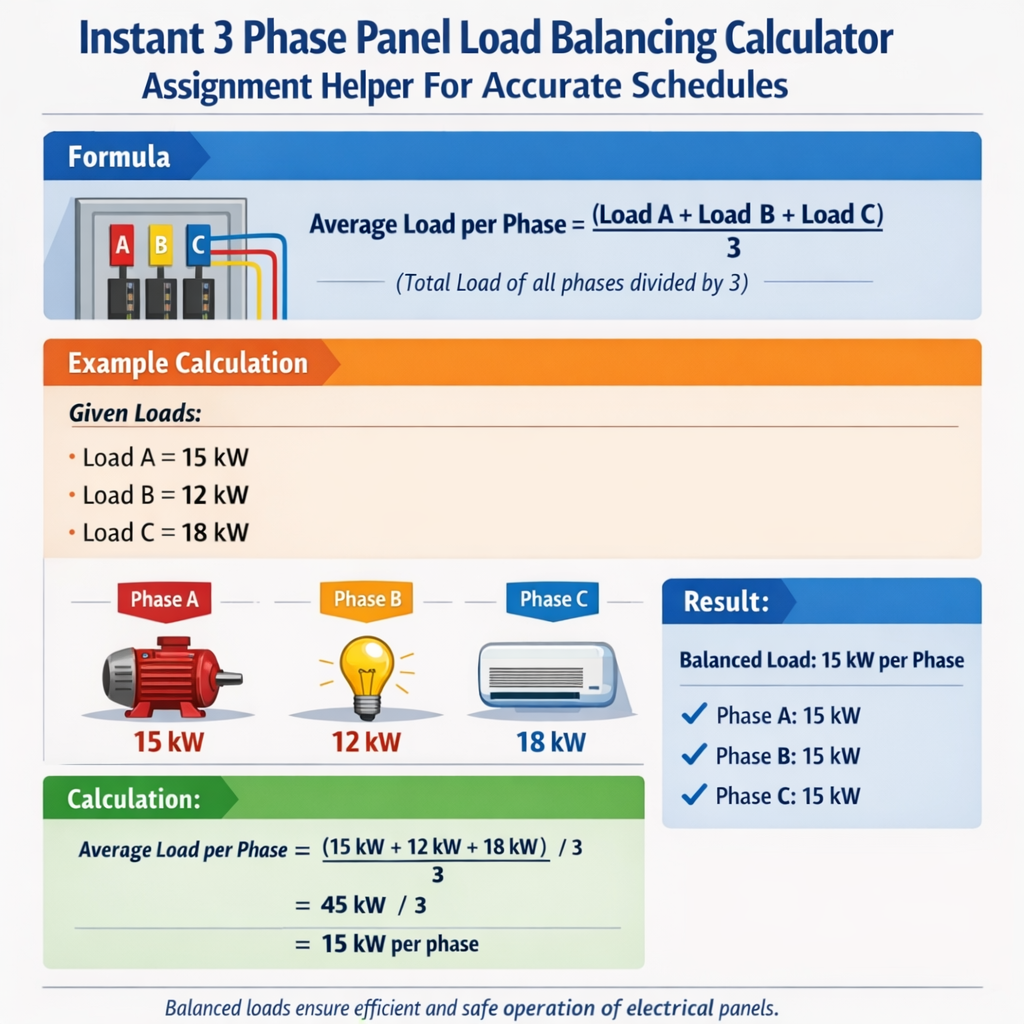
- I_avg — arithmetic mean of phase currents = (I_A + I_B + I_C) / 3 (A).
- Typical acceptable imbalance: less than 10% for many installations; aim for <5% where possible.
I_neutral ≈ |I_A + I_B + I_C| (when sign of currents taken into account)
In balanced systems with 120° phase shifts, the neutral current magnitude is the vector sum of phase phasors. For practical scheduling calculators working with magnitudes, using scalar approximation based on imbalance can suffice.Typical values and standard tables
Below are extensive tables with common values used for quick assignment and verification in calculators. These tables include motor currents, typical single-phase load currents at common voltages, and common breaker ampacity references.| Three-phase Motor Output | Voltage (V) | Typical Efficiency | PF | Approx. Full-Load Current (A) |
|---|---|---|---|---|
| 1.5 kW | 400 | 0.85 | 0.85 | ≈3.0 |
| 5.5 kW | 400 | 0.90 | 0.88 | ≈9.0 |
| 15 kW | 400 | 0.92 | 0.90 | ≈24 |
| 30 kW | 400 | 0.93 | 0.92 | ≈48 |
| 75 kW | 480 | 0.94 | 0.92 | ≈95 |
| 150 kW | 480 | 0.95 | 0.92 | ≈190 |
| Single-phase Load Type | Voltage (V) | Typical Power | Approx. Current (A) |
|---|---|---|---|
| Office Lighting | 230 | 500 W | ≈2.2 |
| Small Split AC | 230 | 3,500 W | ≈15.2 |
| Commercial Microwave | 230 | 2,000 W | ≈8.7 |
| Server Rack (per rack) | 230 | 3,000 W | ≈13.0 |
| Electric Water Heater | 230 | 4,500 W | ≈19.6 |
| Common Breaker Rating | Typical Conductor (Cu) | Ampacity (A) |
|---|---|---|
| 20 A | 12 AWG | 20 |
| 30 A | 10 AWG | 30 |
| 60 A | 6 AWG | 65 |
| 100 A | 3 AWG | 100 |
| 200 A | 2/0 AWG | 195 |
Assignment rules and constraints for the calculator
A practical instant assignment helper enforces constraints when proposing phase assignments and schedules:- Respect each circuit breaker rating and conductor ampacity; do not assign a phase that results in I_phase > breaker rating.
- Account for continuous load derating where applicable (e.g., NEC requires 125% of continuous loads for sizing overcurrent protective devices).
- Consider diversity and demand factors for groups of loads where allowed by code and engineering judgment.
- Preserve single-phase loads that are already tied to a specific phase unless reassignment is permitted and physically feasible.
- For multi-wire branch circuits sharing neutrals, ensure correct phase pairing to avoid excessive neutral currents.
Derating rule example (continuous loads)
When sizing protective devices for continuous loads, apply:Breaker_setting ≥ 1.25 × I_continuous
- I_continuous — continuous load current (A).
- Typical action: compare assigned phase current to adjusted breaker_setting to verify compliance.
Example 1: Commercial HVAC panel — full workflow and solution
Scenario summary:- Panel: 3-phase, 480 V line-to-line, 225 A main breaker.
- Loads to assign: three single-phase rooftop furnaces (R1, R2, R3), two three-phase condensing units (C1, C2), multiple lighting circuits (L1–L4).
- Given nameplate currents:
- R1: single-phase 230 V heating element, 18 A.
- R2: single-phase 230 V heating element, 22 A.
- R3: single-phase 230 V heating element, 14 A.
- C1: three-phase 15 kW, PF 0.9, efficiency 0.92 at 480 V.
- C2: three-phase 7.5 kW, PF 0.88, efficiency 0.90 at 480 V.
- L1–L4: single-phase lighting circuits at 230 V consuming 8 A, 6 A, 10 A, 6 A respectively.
I = (P_kW × 1000) / (√3 × V_LL × η × PF)
I_C1 = (15 × 1000) / (1.732 × 480 × 0.92 × 0.90)
I_C1 ≈ 15,000 / 688.36608 ≈ 21.8 A
C2 current:I_C2 = (7.5 × 1000) / (1.732 × 480 × 0.90 × 0.88)
I_C2 ≈ 7,500 / 658.038 ≈ 11.4 A
Step 2: List single-phase currents mapped to 230 V supply (assumed line-to-neutral on panel phases). Convert nothing else; using given amps.Load list with currents (A):- R1: 18
- R2: 22
- R3: 14
- L1: 8
- L2: 6
- L3: 10
- L4: 6
- C1 (three-phase): 21.8 per phase
- C2 (three-phase): 11.4 per phase
- Phase A: 21.8 + 11.4 = 33.2 A
- Phase B: 21.8 + 11.4 = 33.2 A
- Phase C: 21.8 + 11.4 = 33.2 A
- 22 A → assign to Phase A (lowest any phase equal; choose A): A = 33.2 + 22 = 55.2
- 18 A → lowest phase is B or C (33.2). Assign to B: B = 51.2
- 14 A → lowest is C (33.2). Assign to C: C = 47.2
- 10 A → lowest is C (47.2) vs B (51.2) vs A (55.2) → assign to C: C = 57.2
- 8 A → lowest is B (51.2). Assign to B: B = 59.2
- 6 A → lowest is A (55.2). Assign to A: A = 61.2
- 6 A → lowest is A? Now A=61.2, B=59.2, C=57.2 → assign to C (lowest): C = 63.2
- A = 61.2
- B = 59.2
- C = 63.2
I_avg = (61.2 + 59.2 + 63.2) / 3 = 61.2 A
I_max = 63.2 A
Imbalance% = (63.2 − 61.2) / 61.2 × 100 ≈ 3.27%
Example 2: Industrial motor bank with reassignment optimization
Scenario summary:- Panel: 600 V three-phase, 400 A bus.
- Loads: mix of nine single-phase heaters and four three-phase motors. Objective: reassign single-phase heater circuits among phases to minimize I_max and meet per-phase breaker limits.
- Nameplate currents:
- Heaters H1–H9: [28, 28, 20, 12, 12, 18, 18, 6, 6] A at 230 V.
- Motors M1–M4: three-phase currents per calculation:
- M1: 45 A
- M2: 32 A
- M3: 60 A
- M4: 18 A
- Total motor per-phase = 45 + 32 + 60 + 18 = 155 A added equally? Actually each motor contributes its current to each phase. So each phase receives sum of motor phase currents: 155 A.
- A = 155, B = 155, C = 155
- 28 → A = 183
- 28 → B = 183
- 20 → C = 175
- 18 → C = 193
- 18 → A = 201
- 12 → B = 195
- 12 → B = 207
- 6 → C = 199
- 6 → A = 207
- A = 207
- B = 207
- C = 199
I_avg = (207 + 207 + 199) / 3 = 204.33 A
I_max = 207
Imbalance% ≈ (207 − 204.33) / 204.33 × 100 ≈ 1.31%
This is already excellent. But if per-phase breaker limit were 200 A, phases A and B exceed 200 A. The calculator must also respect breaker limits. To solve, perform constrained reassignment to keep all phases ≤ 200 A.Find swaps to reduce A and B by at least 7 A each. Potential swaps: Move a 6 A heater from A to C reduces A to 201, increases C to 205. Then move a 6 A from B to C? But only two 6 A exist; need combination.Try alternative assignment targeting per-phase ≤ 200: Objective: assign heaters so that A,B,C ≤ 200.Search by hand for a feasible arrangement: Start baseline 155 each. Assign 28 to A (A=183), 28 to B (B=183), 20 to A (A=203) — already over. Maybe distribute:Try:- A: 28, 18, 12 → adds 58 → A = 213 (too high)
- Increase bus rating or feeder to allow higher per-phase capacity
- Relocate some heaters to another panel or shift motor scheduling
- Implement duty-cycle stagger, reduce simultaneous loads
Integration, automation, and schedule generation
An instant three-phase panel load balancing calculator assignment helper typically integrates these features:- User input or database import of load inventory (nameplate currents, kW, PF, continuous flag, existing phase assignment).
- Automated conversion utilities (kW → A) with adjustable η and PF defaults.
- Constraint engine that enforces breaker sizes, conductor ampacity, continuous load derating, and phase assignment locks.
- Assignment optimization module supporting multiple objectives (minimize I_max, minimize variance, respect balancing thresholds).
- Exportable panel schedules in spreadsheet/PDF format with per-circuit phase, breaker, and computed expected current columns.
- Alerting mechanism for violations (e.g., exceeding 80% bus utilization, load shedding recommendations).
- Keep an auditable record of nameplate values and calculation assumptions (PF, η).
- Allow manual overrides and lock certain circuits to phases for legacy or critical equipment.
- Provide visualization of phase currents and an imbalance heat map in the UI to support quick decisions.
- Integrate with building management and preventive maintenance systems to align switching schedules and runtime staggering.
Safety, code compliance, and normative references
Assignment helpers must reference and apply relevant installation standards and safety codes. Key normative references include:- NFPA 70, National Electrical Code (NEC) — provides requirements for sizing conductors and overcurrent protection, continuous load derating, and multi-wire branch circuits. See: https://www.nfpa.org/nec
- IEC 61439 — for low-voltage switchgear and controlgear assemblies, useful when specifying panels and busbar ratings. See: https://www.iso.org/standard/69562.html (IEC standards distribution)
- IEEE Std 141 (Red Book) and IEEE Std 142 (Green Book) — provide guidance on power distribution and grounding practices. See: https://standards.ieee.org/
- Manufacturer motor and HVAC equipment data sheets — for accurate PF and efficiency values.
- Continuous load factor: ensure breaker setpoints account for 125% of continuous current when required by code.
- Neutral loading: warn if neutral current may exceed conductor ampacity for shared neutrals.
- Derating for bundling and ambient temperature: prompt user to apply conductor ampacity derating where applicable (per NEC tables).
Validation, testing, and accuracy assurance
To ensure instant calculators produce reliable schedules:- Perform unit tests on kW-to-A conversions across voltages and PF/η ranges.
- Validate assignment algorithm against a brute-force solver for small sets to confirm optimality.
- Use field-collected load measurements (current clamps, submetering) to calibrate assumed PF and diversity factors.
- Include sensitivity analysis showing how much imbalance changes if a large load is added or removed.
Operational recommendations and mitigation strategies
When imbalance or overload is detected, practical mitigation options:- Physical reassignment of single-phase loads to alternate phases where wiring and panels permit.
- Stagger start times for large motors or HVAC equipment using soft starters or VFDs to limit simultaneous inrush.
- Install additional panels or transfer some loads to adjacent panels to reduce per-bus current.
- Upgrade feeders or bus rating as long-term capacity planning.
Monitoring and continuous improvement
Continuous monitoring enables dynamic scheduling and demand response:- Use smart metering and IoT sensors to feed actual current data back into the balancing algorithm.
- Implement closed-loop adjustments: when measured imbalance exceeds thresholds, the system suggests reassignments or load-shedding actions.
- Record historical patterns and apply machine learning to predict peak combinations and propose preemptive scheduling.
References and further reading
- NEC (NFPA 70) — official code and sizing requirements: https://www.nfpa.org/nec
- IEC 61439 series — low-voltage switchgear and controlgear assemblies: https://www.iso.org/standard/69562.html
- IEEE Power Engineering Resources — standards and application guides: https://standards.ieee.org/
- Manufacturer motor catalogs — example: Siemens motor technical data and conversion tables: https://new.siemens.com/
- Energy management best practices — U.S. Department of Energy, guide to motor systems: https://www.energy.gov/eere/amo/advanced-manufacturing-office
Key takeaways for implementing an instant assignment helper
- Use robust formulas for kW-to-A conversion and imbalance metrics; document assumptions (PF, η, voltage).
- Implement constraint checking for breaker ratings, conductor ampacity, and continuous load derating.
- Offer multiple optimization modes: greedy for instant responsiveness and ILP/metaheuristics for batch optimality.
- Provide detailed panel schedules with phase assignments and per-phase computed currents, and highlight violations.
- Integrate monitoring inputs and normative checks (NEC/IEC guidance) to maintain safety and compliance.