This technical guide explains NEC-compliant grounding configurations for unit substations and service disconnect inputs clearly.
Scope includes electrode systems, GEC sizing, bonding methods, fault calculations, and real-world implementation examples today.Grounding configuration and minimum grounding conductor sizing for service vs separately derived unit substation (thermal method)
Regulatory framework and core definitions
Grounding and bonding for unit substations and service disconnect inputs must be designed to satisfy the National Electrical Code (NEC), applicable local amendments, and recognized engineering standards. Key NEC sections to consult include NEC 250 (Grounding and Bonding), NEC 230 (Services), NEC 408 (Switchboards, Switchgear, and Panelboards), and the rules addressing separately derived systems in NEC 250.30. Complementary guidance: IEEE Std 142 (Green Book) and IEEE Std 80 for grounding of substations.Important definitions used throughout:- Service: The conductors and equipment for delivering electric energy from the serving utility to the wiring system of the premises (NEC art. 100).
- Service disconnecting means (SDS): The disconnect or set of disconnects required at the service point to de-energize the premises.
- Service equipment: The equipment, such as meter and main service disconnect, where the grounded conductor is connected to the grounding electrode system.
- Unit substation: A factory-assembled packaged assembly that typically includes a transformer and switchgear, provided as a single unit for building or site distribution.
- Separately derived system: A system where the neutral is not connected to the supply-side neutral (e.g., a transformer with a separately grounded neutral) and that requires its own grounding/bonding arrangements per NEC 250.30.
Fundamental grounding principles for unit substations versus SDS
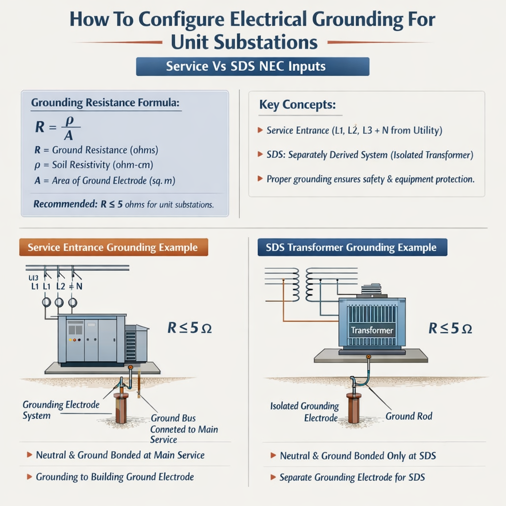
A clear engineering decision: where to bond the grounded conductor (neutral) to the grounding electrode system. This determines fault return paths, equipment grounding conductor routing, and protective device coordination.Service equipment bonding location
- When the unit substation is configured as service equipment (the utility service terminates at the substation with main overcurrent protection and service disconnecting means located in the substation), the neutral-to-ground bond must be made at that service equipment location (single bonding point for the service). NEC 250.24(A)(1) requires the grounded conductor be connected to the grounding electrode system at the service equipment. - From that service bonding point, equipment grounding conductors (EGCs) must be run with the associated circuits back to the bonded enclosure. Do not establish multiple neutral-to-ground bonds downstream in the same service system.Separately derived system (SDS) considerations
- If the unit substation contains a transformer that establishes a separately derived system (the secondary neutral is not directly connected to the utility neutral and has a separate neutral conductor established by the transformer), then the bonding of the neutral to the grounding electrode system must occur at the SDS neutral bonding location (NEC 250.30). - For SDS installations the transformer neutral is normally bonded to the grounding electrode conductor (GEC) at the transformer enclosure and the grounding electrode system must be sized and connected per NEC 250.30(A) and 250.32. The service-side bonding point and SDS-bonding are two distinct bonding points separated by the service point or transformer, per NEC rules.Components of the grounding electrode system and typical sizing
The grounding electrode system for unit substations may include one or more of the following (NEC 250.50–250.68):- Driven ground rods
- Grounding electrode conductor (GEC) connecting to electrodes
- Concrete-encased electrodes (Ufer grounds)
- Ground ring or grid
- Metal underground water piping in direct contact with earth for 10 ft or more
- Plate electrodes
| Electrode Type | Typical Minimum Size | Typical Installation Notes | Target Resistance |
|---|---|---|---|
| Driven Rod | 8 ft × 5/8 in copper-clad steel or listed rod | Install at least 6 ft from other electrodes; multiple rods in series/parallel to reduce resistance | <25 Ω desirable; <5 Ω preferred for critical substations |
| Concrete-encased electrode (Ufer) | 20 ft of #4 bare copper or rebar encased in concrete | Reliably low resistance in most soils; often used for building foundations | <10 Ω typical; excellent long-term stability |
| Ground ring | 2 AWG copper or larger buried 2–3 ft deep around building perimeter | Used to interconnect electrodes and reduce grid resistance | <5 Ω achievable subject to soil resistivity |
| Plate electrode | 1/4 in × 2 ft × 2 ft copper plate | Used where rods cannot be driven or soil resistivity is high | Depends on plate area and soil; often higher than Ufer unless large |
Sizing GEC and EGC: methods, formulas, and explanations
Two separate conductor sizing concerns:- GEC (Grounding Electrode Conductor): connects service or transformer neutral bond to the grounding electrode system (NEC 250.66, 250.64).
- EGC (Equipment Grounding Conductor): carries fault current from equipment to the overcurrent device; sized per NEC 250.122 and run with circuits.
Basic fault current estimate (prospective short-circuit current)
Explanation of variables:
- V_LL — nominal line-to-line voltage on the system secondary (e.g., 480 V for 480Y/277 V systems).
- Z_s — total system impedance seen by a fault at the point of interest (ohms), including transformer impedance, conductor impedance, and utility source impedance.
Formula: I_sc ≈ (Transformer kVA × 1000) / (√3 × V_secondary × Z_percent/100)
Variables:
- Transformer kVA — transformer rated apparent power in kVA.
- V_secondary — line-to-line voltage on the secondary (V).
- Z_percent — transformer percent impedance (typical 4–8% for medium- to large-power transformers).
GEC sizing methodology (procedural)
- Step 1: Identify whether the connection is at a service equipment or an SDS (NEC 250.24, 250.30). The GEC originates at the bonded enclosure. - Step 2: Use the largest ungrounded service-entrance conductor or equivalent to determine minimum GEC per NEC 250.66 (NEC provides a table based on cross-sectional area). When conductors are paralleled, calculate equivalent area accordingly. - Step 3: Provide a GEC conductor continuous, with listed connectors, to the grounding electrode system. Increase conductor size where required by mechanical protection or multiple electrodes. - Step 4: Where the ground electrode conductor must be run to remote electrodes, increase size for length and potential short-circuit heating concerns, and consider parallel electrodes to reduce resistance.| Typical Service Rating (A) | Common GEC (Copper) — engineering practice | Common GEC (Aluminum) — engineering practice | Typical EGC for feeder (per 250.122 reference) |
|---|---|---|---|
| 100 A | #8 AWG Cu | #6 AWG Al | #8 Cu (for 60 A devices) or #8 Cu when protective devices <100 A |
| 200 A | #4 AWG Cu | #2 AWG Al | #6 to #4 Cu depending on OCPD (see NEC 250.122) |
| 400 A | #2 AWG Cu | 1/0 AWG Al | #3/0 Cu or #2 Cu approaches depending on short-circuit and OCPD |
| 1200 A | 250 kcmil Cu (typical practice) | 350–400 kcmil Al (typical) | Consult NEC 250.122 and engineering analysis for high ratings |
Equipment grounding conductor sizing and time‑current withstand
The EGC must be sized to safely carry fault current long enough to trip the overcurrent device without damage. NEC 250.122 provides the minimum EGC sizes for different OCPD ratings. Use the NEC table directly for compliance. Where conductors will see high fault currents or prolonged thermal stress, select larger EGCs or use parallel bonding paths (bonding jumpers, ground rings) as required.Ground grid and electrode resistance calculations
Two useful empirical formulas appear in engineering practice:Approximate resistance of a single driven rod (ohms):
R_rod ≈ (ρ / (2 × π × L)) × (ln(4 × L / d) − 1)
Variables:- R_rod — approximate resistance of single rod (Ω).
- ρ (rho) — soil resistivity (Ω·m or Ω·ft, keep units consistent).
- L — length of rod (m or ft, consistent with ρ).
- d — diameter of rod (m or ft).
- ρ: common soils: 100 Ω·m (sandy loam) to 1000 Ω·m (dry rock). In US customary units: 300–3000 Ω·ft.
- L: 2.4 m (8 ft) typical rod length.
- d: 0.016 m (5/8 in) for typical rods.
| Soil Resistivity (ρ) | Single 8 ft Rod R_rod (approx) | Two rods (spaced 8 ft) | Four rods (spaced 8 ft) |
|---|---|---|---|
| 100 Ω·m (~328 Ω·ft) | ~20–25 Ω | ~7–10 Ω | ~3–4 Ω |
| 300 Ω·m (~984 Ω·ft) | ~60–75 Ω | ~20–30 Ω | ~8–12 Ω |
| 1000 Ω·m (~3280 Ω·ft) | ~200–300 Ω | ~70–100 Ω | ~25–40 Ω |
Installation, testing and commissioning steps
Follow a defined sequence:- Survey soil resistivity (Wenner test) at proposed substation site and produce layered resistivity profile.
- Determine system configuration: service neutral bonding vs SDS neutral bond at transformer.
- Design grounding electrode system (grid, rods, Ufer, ring) sized to meet target resistance and step-and-touch criteria.
- Select GEC and EGC sizes according to NEC tables and engineering analysis; coordinate with overcurrent protection device ratings and prospective fault currents.
- Install mechanical protections for exposed conductors (conduit, sleeves), and use listed connectors and bonding jumpers as required (NEC 250.8 & 250.70).
- Perform clamp torque checks, continuity verification, and megger testing on electrodes constructed as needed.
- Measure final ground resistance (fall-of-potential) and document step-and-touch potentials, retaining test reports and drawings.
Practical bonding, conductor routing, and common pitfalls
Key installation notes:- Avoid multiple neutral-to-ground bonds on the service side of the SDS; this can create parallel neutral paths and nuisance currents on grounding system components.
- Run the GEC with as straight and short a route as practicable; avoid splicing unless using listed connectors and protective enclosures.
- Use exothermic welds or listed compression connectors for permanent electrode bonding when practicality allows.
- Bond structural steel and metallic enclosures to the grounding electrode system to prevent elevated potentials during fault events (NEC 250.104).
- Provide adequate mechanical protection for GEC and EGCs where subject to mechanical damage (NEC 250.64, 250.66).
- Document labeling: identify neutral-ground bond location and provide one-line diagrams showing the bonding arrangement and electrode connections.
Real-world example 1: Unit substation as service equipment — 1000 kVA, 480Y/277V secondary
Project data:- Transformer: 1000 kVA, 480Y/277 V secondary, transformer percent impedance Z% = 5.75% (typical).
- Service configuration: utility primary to transformer primary — unit substation is service equipment; neutral bond at transformer switchgear enclosure.
- Design target: provide robust grounding for personnel safety and fault clearing, target grounding electrode resistance <10 Ω, prefer <5 Ω.
Formula: I_sc ≈ (Transformer kVA × 1000) / (√3 × V_secondary × Z_percent/100)
Calculation:I_sc ≈ 1,000,000 / (831.4 × 0.0575) ≈ 1,000,000 / 47.79 ≈ 20,935 A
Interpretation: prospective fault current available at the secondary connection, before feeder impedance, about 21 kA from transformer.Step C — GEC and EGC sizing approach:- Identify largest ungrounded conductor (secondary bus feeding switchgear designed for 1203 A). Using NEC 250.66 or equivalent, select minimum GEC. For engineering selection, choose copper GEC not smaller than #2 AWG for high-amperage feeders commonly encountered — but refer to local NEC table for legal minimum.
- Equipment grounding conductor sizing for feeders: use NEC 250.122 table relative to the OCPD protecting the feeder conductors. For a 1600–2000 A main, typical practice is to provide large copper conductor (e.g., 4/0 Cu or larger) sized per NEC and mechanical/thermal requirements.
- Soil resistivity test: assume layered soils: top layer 200 Ω·m, deeper 500 Ω·m. Use a ground ring with multiple rods and Ufer where possible.
- Design a perimeter ground ring (2 AWG Cu) plus two 8 ft rods and a Ufer connection to foundation rebar to achieve <5 Ω in typical conditions.
- Measure fall-of-potential and document final ground resistance. If results exceed targets, add rods or extend grid.
- Test continuity between neutral bond and each major conductive structure and record results.
Real-world example 2: Separately derived system inside unit substation feeding a building SDS
Project data:- Transformer: pad-mounted 750 kVA with high-voltage primary and 208Y/120 V secondary feeding building distribution via a unit substation interior switchboard configured as a separately derived system (neutral created at transformer).
- SDS location: building main service and utility connection are upstream; transformer secondary is separately derived and must have its neutral bonded at the transformer or the first disconnecting means at the SD system per NEC 250.30.
I_sc ≈ 750,000 / (360.3 × 0.055) ≈ 750,000 / 19.816 ≈ 37,840 A
Interpretation: transformer provides significant available fault current at the secondary.Step C — bonding strategy:- Because the transformer secondary is a separately derived system, bond the secondary neutral at the transformer enclosure to a dedicated grounding electrode conductor which ties into the grounding electrode system serving the building per NEC 250.30(A).
- Ensure the neutral is isolated from the service neutral upstream — do not create parallel neutral-to-ground bonds downstream of the service point.
- Run a GEC from the transformer neutral/bond point to the electrode system: use listed connectors and protect the conductor mechanically where exposed.
- Size the GEC according to NEC 250.66 for the transformer secondary conductor size; for high-current systems, use a larger conductor (for example, 4/0 Cu or larger) as required by both code and thermal fault analysis.
- Confirm that the feeder and branch protective devices will operate to clear the calculated fault currents without allowing excessive thermal stress on the EGCs. If necessary, select inverse-time coordination curves and verify clearing times.
- Confirm neutral-to-ground bond is made only at the SDS bond point and record the physical location.
- Document GEC routing and verify electrode resistance by fall-of-potential testing.
- Prepare one-line diagrams showing bonding arrangement to satisfy inspection and maintenance requirements.
Testing, inspection and record-keeping
Essential tests and records:- Soil resistivity test report with raw data and interpreted layered model.
- Fall-of-potential results and instrument calibration certificate.
- Continuity and clamp torque checklist for all bonded connections.
- Short-circuit calculations and protective device coordination study showing clearing times and I^2t exposures for GEC/EGC selection.
- As-built drawings with conductor sizes, materials, and bond point locations labeled.
References and external authoritative resources
- NFPA 70, National Electrical Code (NEC) — official code (see especially Article 250, Article 230, Article 250.30). https://www.nfpa.org/
- IEEE Std 142 — IEEE Green Book: Grounding of Industrial and Commercial Power Systems (conceptual and grounding design). https://standards.ieee.org/
- IEEE Std 80 — Guide for Safety in AC Substation Grounding (substation grid, step-and-touch limitations). https://standards.ieee.org/
- U.S. Department of Labor, OSHA — Electrical safety and grounding basics for buildings. https://www.osha.gov/
- International Association of Electrical Inspectors (IAEI) — practical guidance and articles on NEC interpretation. https://www.iaei.org/
Final technical recommendations
- Always identify whether the unit substation is service equipment or constitutes a separately derived system; this dictates the bonding location.
- Perform soil resistivity testing early in design to size electrodes and grid effectively; design for step-and-touch potential compliance per IEEE Std 80.
- Derive GEC and EGC sizes from NEC tables, but validate selections against calculated prospective fault currents and thermal I^2t exposures.
- Use robust mechanical connectors and list-approved clamps; prefer exothermic bonding where practicable for permanent, low-resistance connections.
- Document all bonding, conductor routings, tests, and one-line diagrams for AHJ review and long-term maintenance.