Accurate excavation volume calculation reduces cost, risk and schedule deviations on construction projects globally safely.
This guide describes methodologies, formulas and practical tools for effortless, reliable excavation volume computations daily.
Excavation Volume Calculator — Efficient Technical Estimation
Purpose and practical value for engineering and site management
Excavation volume calculation is a core civil engineering activity that directly affects procurement, equipment selection, transportation planning, and earthworks cost estimation. Errors cascade into bid overruns, site delays and increased safety exposure.
The objective here is to present deterministic and empirical calculation methods, practical correction factors, and worked examples that are ready for professional use on international projects.
Core methods to compute excavation volume
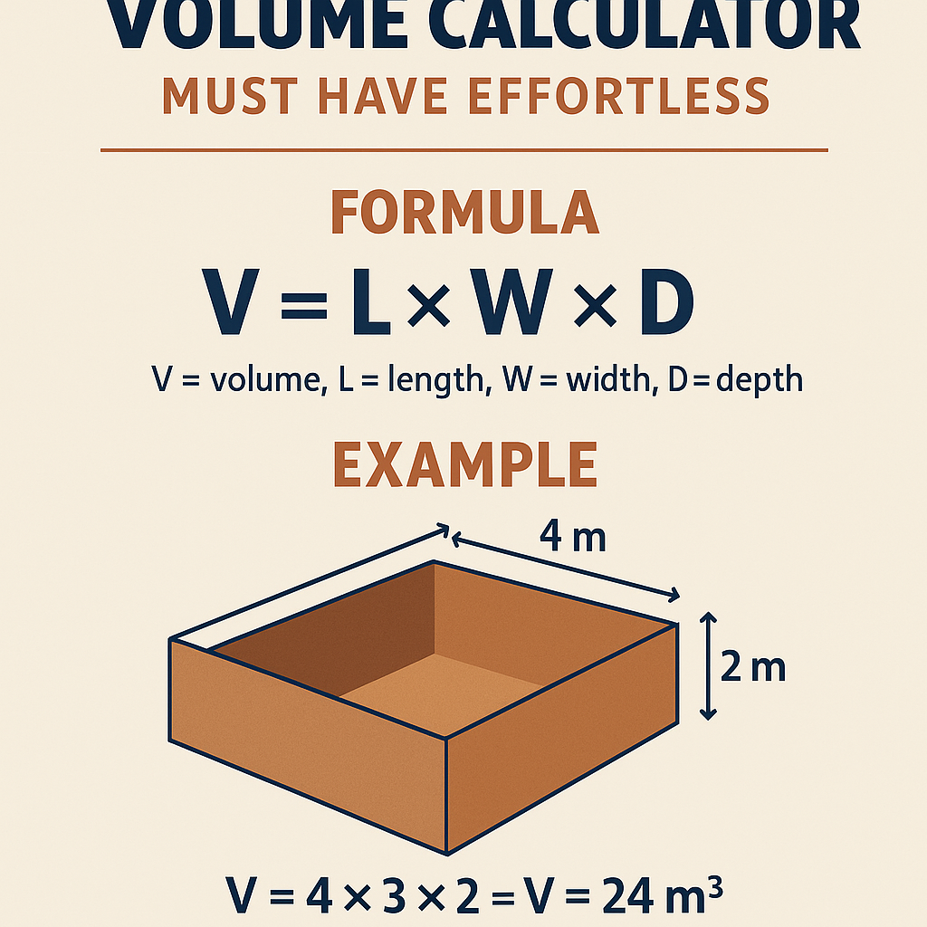
Rectangular prism (block) method
Use this for simple trenches, pads and pits with vertical faces.
Variables:
- Length (L): linear extent along excavation (typical units: m or ft)
- Width (W): average width of excavation (m or ft)
- Depth (D): average excavation depth (m or ft)
Typical values: L = 50 m (small site), W = 1.2 m (utility trench), D = 2.0 m (service depth).
Trapezoidal cross-section (average end-area) method
Appropriate for channels, embankment cuts, and constant slope excavations.
Variables:
- A1, A2: cross-sectional areas at each end (m² or ft²)
- L: length between sections (m or ft)
A common simplification sets A1 = A2 for uniform cross-section: Volume = A × L.
Prismoidal formula (accurate for curved or varying cross-sections)
Use when cross-sectional areas vary smoothly along length. This is the most accurate analytic method for linear segments.
Variables:
- L: length of segment
- A1: area at start section
- Am: area at mid-section
- A2: area at end section
Typical use: long excavations with changing slopes or benching where end areas differ.
Factors that modify theoretical volumes
Swell and shrinkage factors
Excavated material changes volume when removed and when placed and compacted. Account for both to estimate haul and fill requirements.
Definitions:
- Swell factor (S): percentage increase in loose volume relative to in-situ volume. Example expression: Loose Volume = In-situ Volume × (1 + S)
- Shrinkage/compaction factor (C): percentage reduction when material is compacted in fill. Example expression: Compacted Volume = Loose Volume × (1 − C)
| Material type | Typical in-situ unit weight (kN/m³) | Typical in-situ unit weight (lb/ft³) | Swell factor (typical) | Shrinkage/Compaction factor (typical) |
|---|---|---|---|---|
| Silty clay (moist) | 18–20 | 115–125 | 10–25% | 10–20% |
| Sandy/gravelly soils | 17–20 | 110–125 | 15–30% | 5–15% |
| Highly organic soil | 12–16 | 75–100 | 30–60% | 20–40% |
| Weathered rock / coarse rubble | 21–24 | 135–150 | 5–15% | 10–25% |
Slope batter, benching and added width
Open-cut slopes increase the surface footprint and therefore the volume. Compute cross-section considering side slopes or bench widths.
For a trench with bottom width Wb, depth D, and side slope ratio of H:V = s (horizontal:vertical), the top width Wt = Wb + 2 × s × D and cross-sectional area A = D × (Wb + Wt) / 2.
Variables:
- Wb: bottom width
- D: depth
- s: horizontal run per unit vertical (e.g., 1.5 means 1.5 horizontal to 1 vertical)
- Wt: top width
Unit conversions and common constants
| From | To | Conversion factor |
|---|---|---|
| m³ | ft³ | 1 m³ = 35.3147 ft³ |
| m³ | yd³ | 1 m³ = 1.30795 yd³ |
| ft³ | yd³ | 1 yd³ = 27 ft³ |
| kN/m³ | lb/ft³ | 1 kN/m³ ≈ 6.365 lb/ft³ |
Formulas, variable definitions and typical values
Basic rectangular prism
Variable definitions and typical values:
- L (Length): 10–500 m depending on project segment
- W (Width): 0.6–10 m (trench to pad)
- D (Depth): 0.3–8 m for common earthworks; >8 m usually requires engineered shoring
Trench with side slopes
Typical slope values (horizontal:vertical):
- Stable rock: s ~ 0 (vertical)
- Type A cohesive soils: s ≈ 1/2 to 1 (dependent on moisture)
- Type B soils: s ≈ 1 to 1.5
- Type C granular soils: s ≈ 1.5 to 2
Prismoidal formula expanded
Where:
- L: segment length
- A1: area at station start
- Am: area at mid-station (precise mid-point)
- A2: area at station end
Typical approach: subdivide long excavations into segments where areas are measured or computed.
Estimating haul, equipment productivity and cycle counts
To plan work and tender accurately, translate in-situ volumes to loose volumes, then to truckloads and machine cycles.
- Loose Volume = In-situ Volume × (1 + S) where S = swell fraction (as decimal)
- Tonne conversion: mass = Volume × unit weight (kN/m³ corresponds to approx mass kg/m³ using g)
- Truckloads = Loose Volume / truck capacity (m³)
| Machine/Truck | Typical capacity (m³ loose) | Cycle time range (min) typical | Notes |
|---|---|---|---|
| Mini-excavator 2–3 t | 0.03–0.08 | 0.5–2 | Tight sites, low productivity for deep trenches |
| Hydraulic excavator 20 t | 0.8–1.5 | 1–4 | Common for medium earthworks |
| Wheel loader 4 m³ bucket | 3–4 | 0.8–3 | Used for short hauls to trucks |
| Articulated dump truck | 8–12 | N/A | Used for off-road haulage; capacities vary |
Real-case worked example 1: Utility trench with sloped sides and swell factor
Project data
- Length L = 120 m
- Bottom width Wb = 1.0 m (pipe trench)
- Depth D = 2.5 m
- Side slope s = 1.5 (horizontal per vertical) (typical for granular soil)
- Swell factor S = 0.20 (20%) for sandy soil
- Truck capacity = 8 m³ (loose)
Step-by-step calculation
- Compute top width:
Wt = Wb + 2 × s × D = 1.0 + 2 × 1.5 × 2.5 = 1.0 + 7.5 = 8.5 m
- Compute cross-sectional area (trapezoid):
A = D × (Wb + Wt) / 2 = 2.5 × (1.0 + 8.5) / 2 = 2.5 × 9.5 / 2 = 2.5 × 4.75 = 11.875 m²
- Compute in-situ volume:V_in_situ = A × L = 11.875 × 120 = 1,425 m³
- Compute loose volume after excavation:V_loose = V_in_situ × (1 + S) = 1,425 × 1.20 = 1,710 m³
- Estimate truckloads:Truckloads = V_loose / capacity = 1,710 / 8 ≈ 213.75 → round up to 214 truckloads
Summary: In-situ volume = 1,425 m³; loose volume = 1,710 m³; required truckloads ≈ 214.
Real-case worked example 2: Basement excavation using prismoidal method with differing end areas
Project data
- Basement plan: rectangular footprint varying lengthwise; consider a 30 m segment
- Segment length L = 30 m
- Cross-section at start A1 = 80 m² (shallower end)
- Cross-section at mid Am = 95 m²
- Cross-section at end A2 = 110 m² (deeper end)
- Swell factor S = 0.15 (15%) for mixed clay-sand
Step-by-step calculation
- Apply prismoidal formula:V_segment = (L / 6) × (A1 + 4 × Am + A2)
V_segment = (30 / 6) × (80 + 4 × 95 + 110) = 5 × (80 + 380 + 110) = 5 × 570 = 2,850 m³
- Total in-situ volume for the whole basement (suppose there are 4 such segments of similar variation) = 2,850 × 4 = 11,400 m³
- Loose volume:V_loose = 11,400 × 1.15 = 13,110 m³
- Consider compaction for backfill where reused: if compaction factor C = 0.10, compacted volume = V_loose × (1 − C) = 13,110 × 0.90 = 11,799 m³
Summary: Per 30 m segment, V = 2,850 m³. For 4 segments: in-situ 11,400 m³, loose 13,110 m³, compacted 11,799 m³.
Accuracy improvements and best practices for measuring areas
- Use survey-grade cross sections at regular intervals (e.g., 5–10 m) to capture variability and reduce interpolation errors.
- Prefer prismoidal results for long segments where cross-sections change; otherwise use average end-area for short consistent runs.
- Document all assumed swell/shrink factors and soil unit weights with laboratory or referenced site investigation data.
- Include allowances for rock excavation: drill-and-blast or ripper productivity is much lower and swell factors are small but require specialist pricing.
Common pitfalls and how to avoid them
- Forgetting side slope contributions: Always compute top width for open cuts
- Neglecting swell factors: Leads to underestimation of haul and stockpile capacity
- Mixing units: Keep consistent units (SI recommended) and apply conversions at the end
- Assuming uniform soil: Use geotechnical logs to subdivide volumes by material type
Regulatory, safety and contractual references
Adopt standards and regulations to ensure engineering rigour and worker safety when planning excavation works. Key authorities and normative references include:
- OSHA — Excavations Standard: https://www.osha.gov/excavations (U.S. occupational safety rules)
- ASTM D2487 — Standard Practice for Classification of Soils: https://www.astm.org/Standards/D2487.htm
- ISO 14688 — Geotechnical investigation standards: https://www.iso.org/standard/ (search ISO 14688)
- British Standards Institution — BS 6031: Code of practice for earthworks (purchase/licensed access)
- US Army Corps of Engineers — EM 1110-1-1804 (Earthwork methods) for practical guidance
These references guide soil classification, shoring design, slope selection and safe excavation practice. Contractual provisions (e.g., FIDIC, NEC) may specify measurement and payment rules for excavations and should be followed.
Practical checklist for implementing an effortless excavation calculation workflow
- Gather geotechnical logs and laboratory densities.
- Survey existing ground and mark control lines for cross-sections.
- Decide segmentation length based on variability (shorter segments for variable profiles).
- Select calculation method: rectangular, end-area or prismoidal.
- Apply slope and batter to compute cross-sections where necessary.
- Apply swell, moisture and compaction factors per material type.
- Convert to operational metrics: truckloads, machine cycles, haul times.
- Document assumptions, tolerances and contingency allowances for bids.
Advanced considerations for optimization and automation
Modern workflows use digital terrain models (DTMs) and GIS to compute cut-and-fill automatically. Implementing a BIM or earthworks modelling process will reduce manual error and allow scenario analysis with variable swell/shrink parameters.
- Use DTM surfaces for existing and design grades and compute cut/fill inter-surface volumes.
- Run sensitivity analysis on swell factors, slope changes and subgrade tolerances.
- Integrate productivity models for equipment allocation and schedule generation.
Quality assurance for excavation measurement
Peer-review key assumptions and spot-check volumes with independent survey surveys. Keep records of all field measurements and calculation spreadsheets for audit and contractual purposes.
Further reading and authoritative links
- Occupational Safety and Health Administration (OSHA) — Excavations: https://www.osha.gov/excavations
- ASTM International — Soil classification standards: https://www.astm.org/
- International Organization for Standardization (ISO) — Geotechnical standards: https://www.iso.org/committee/54902.html
- US Army Corps of Engineers — Engineering Manuals and Technical Letters: https://www.usace.army.mil/
- Federal Highway Administration (FHWA) — Earthwork and geotechnical practices: https://www.fhwa.dot.gov/engineering/geotech/
Key takeaways for effortless, defensible excavation estimates
- Select the correct analytic method for your geometry: rectangular for simple pits, prismoidal for variable sections.
- Always include swell and compaction factors and keep them traceable to lab results or geotechnical reports.
- Convert volumes to operational metrics early: truckloads, cycle counts, and machine hours drive cost and schedule.
- Use surveying and digital modelling to reduce interpolation error; document everything for contractual accountability.
By applying the formulas and workflows above, practitioners achieve more reliable excavation volumes and more predictable project outcomes. Always cross-validate assumptions with geotechnical data and regulatory guidance before finalizing estimates.