This article guides engineers through selecting IEC contactors using a streamlined, accurate calculator methodology reliably.
Calculator focuses on thermal, electrical, and mechanical constraints to ensure safe, compliant industrial operation reliability.
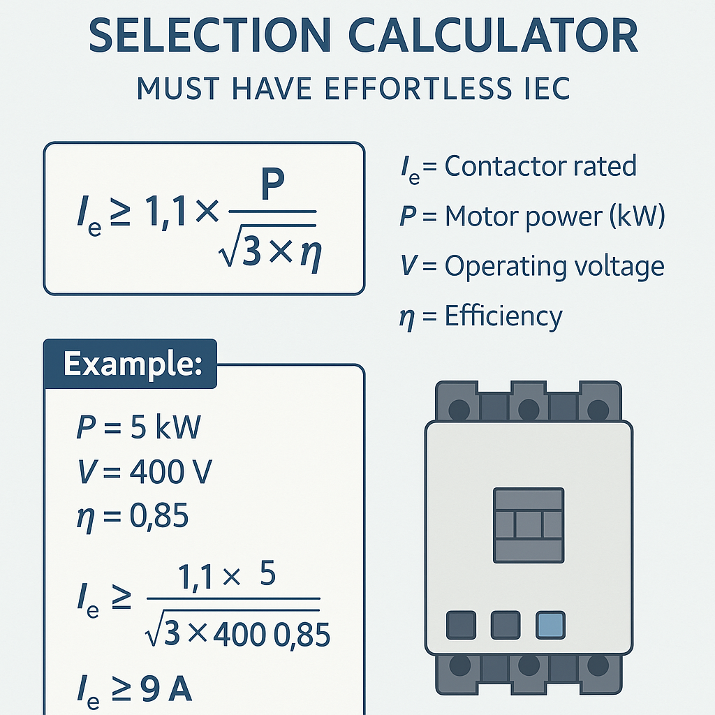
Contactor Selection Calculator — Must Have Effortless IEC
Contactor Selection Calculator: IEC-focused essentials and goals
A contactor selection calculator must translate IEC normative requirements into deterministic calculations that designers can trust. The objective is to convert motor and load data, supply characteristics, and utilization categories into a recommended contactor part family, rated operational current, coil voltage, and auxiliary requirements.
This document outlines the required inputs, formulas, decision logic, verification checks, and two worked examples with complete numeric solutions. It also maps back to IEC normative clauses and authoritative manufacturer datasheets for verification.
Required inputs for an effortless IEC-compliant calculator
- Supply data: line-to-line voltage (V), number of phases, frequency (Hz), available short-circuit current (Isc) at point of installation.
- Load data: continuous power (P) or rated current (if provided), load type (induction motor, resistive heater, capacitive bank, lighting), rated power factor (PF) and efficiency (η) for motors.
- Utilization category: AC-1, AC-3, AC-4 etc. (select based on load type and switching duty).
- Duty cycle: number of operations per hour, on-time %, mechanical endurance expectations.
- Auxiliary requirements: coil control voltage, desired contactor accessories (auxiliary contacts, mechanical interlocks, surge suppression).
- Environmental conditions: ambient temperature, altitude (derating factors), enclosure type (IP rating).
Key IEC concepts and selection constraints
Rated operational current (Ie) and utilization categories
IEC 60947-4-1 defines utilization categories for contactors. Typical application mapping:
- AC-1: Non-inductive or slightly inductive loads (resistive furnaces, heaters).
- AC-3: Switching of squirrel-cage motors: make and break during running, break not during starting (typical motor starters).
- AC-4: Switching of motors with starting and plugging or inching operations (higher mechanical and electrical stress).
Select Ie such that the contactor's rated operational current in the chosen utilization category equals or exceeds the calculated load current, with verification of making and breaking capacities per IEC tables.
Motor starting currents and practical multipliers
For induction motors, locked-rotor (starting) currents are substantially higher than full-load currents. Typical multipliers of rated current (I_FL) at nominal voltage:
| Motor type / condition | Typical multiplier × I_FL | Notes |
|---|---|---|
| Squirrel-cage induction (direct on line start) | 6 – 8 | Typical locked-rotor current 6–8 × I_FL, depends on motor design |
| Squirrel-cage induction (star-delta start) | 2 – 3 (in star) | Reduced during star step; transition must be handled |
| Slip-ring induction | 3 – 6 | External resistance controls starting |
| Permanent magnet motors (inverter-fed) | 1 – 2 | Depends on inverter control; inrush typically low |
| Resistive loads (AC-1) | 1 | No significant inrush |
Essential formulas and variable definitions (HTML-only formulas)
All formulas below are provided using plain HTML-friendly notation. After each formula the variables are explained and typical values are shown.
1) Full-load current for a three-phase motor
- I_FL: full-load current (A)
- P: mechanical output power (W). Typical values: convert kW to W by ×1000.
- sqrt(3): square root of 3 (≈1.732)
- V: line-to-line voltage (V), typical 400 V or 480 V
- η: motor efficiency (decimal). Typical 0.85–0.95 depending on size and IE class
- PF: power factor (decimal). Typical 0.8–0.95 at rated load
I_FL = 30000 / (1.732 × 400 × 0.92 × 0.88) = numeric result computed in worked example below.
2) Required contactor selected current accounting for utilization category
Where I_controlling_condition encapsulates starting or steady-state switching conditions. For AC-3 (motor starter) I_req ≥ I_FL but contactor must be rated for mechanical/electrical endurance and making currents.
3) Short-circuit prospective current approximation
- I_sc: prospective short-circuit current at point of installation (A)
- U_ll: nominal line-to-line voltage (V)
- Z_th: Thevenin equivalent impedance of supply seen at the installation (Ω)
Typical use: verify that contactor's rated making current and peak withstand (I_pk) are sufficient, or that protection clears faults before contactor damage.
4) Thermal overload relay setting
- Correction factors include ambient temperature derating, conductor grouping, altitude.
- Typical relay is set to I_FL for motor protection; verify thermal class and trip characteristics as per IEC 60947-4-1.
Calculator algorithm and decision flow
- Input capture: supply, load, duty, utilization category, environment.
- Compute I_FL using P, V, η, PF if current not directly provided.
- Compute starting current estimate: I_start = multiplier × I_FL (select multiplier from table per motor type).
- Select candidate contactor rated Ie in chosen utilization category such that Ie ≥ I_FL.
- Check making capacity: contactor making current rating must exceed I_start (or manufacturer declared inrush capability).
- Verify breaking capacity at supply supply voltage and available fault current; confirm with IEC 60947-4-1 making/breaking tables from manufacturer documentation.
- Determine coil control voltage and electrical consumption; verify control circuit fuse and driver capability.
- Apply environmental derating (ambient temperature, altitude). If derating requires a larger Ie, upgrade contactor size.
- Output: recommended contactor family/type, IEC-rated Ie, coil voltage, required accessories, part numbers and verification checklist.
Typical manufacturer data points useful for the calculator
| Parameter | Typical values | Design impact |
|---|---|---|
| Rated operational current (Ie) AC-3 | 9 A, 12 A, 18 A, 25 A, 32 A, 40 A, 63 A, 95 A, 125 A, 170 A, 225 A | Choose minimal Ie ≥ I_FL to avoid overheating and excessive wear |
| Making capacity (I_m) | Short-time making currents up to several kA for low-power contactors; large contactors rated for higher values | Must exceed motor inrush or prospective short-circuit peak |
| Coil control voltages | 24 Vdc, 48 Vdc, 110 Vdc, 24 Vac, 48 Vac, 110 Vac, 220–240 Vac | Choose coil matching control supply; consider inrush and holding currents |
| Coil power consumption | Typical 0.5 W – 5 W for DC coils holding (electronic), 1–10 W for AC coils | Affects control transformer sizing and driver transistor losses |
| Mechanical endurance | 1×10^5 to 1×10^7 operations | Depends on duty cycle and contactor class; choose accordingly |
Worked example 1: Sizing a contactor for a 30 kW three-phase motor (400 V)
Objective: Determine an IEC contactor selection for a 30 kW, 3-phase, 400 V motor, assuming AC-3 utilization and direct-on-line start.
Given data
- P = 30 kW (mechanical output)
- V = 400 V line-to-line
- η = 0.92 (typical IE2/IE3 motor at rated load)
- PF = 0.88 (typical at rated load)
- Utilization category = AC-3
- Ambient temperature = 30 °C (no derating beyond standard)
- Locked-rotor multiplier assumed = 6.5 × I_FL (typical DOL)
Step 1: Calculate full-load current I_FL
Compute denominator: 1.732 × 400 × 0.92 × 0.88 = 1.732 × 400 = 692.8; 692.8 × 0.92 = 637.376; 637.376 × 0.88 = 560.889
Step 2: Select candidate contactor rated operational current (Ie)
IEC contactor standard sizes (typical): 40 A, 63 A, 95 A. Since I_FL = 53.5 A, select next higher standard Ie in AC-3: 63 A.
Step 3: Verify making/starting requirements
Estimated starting current I_start = 6.5 × I_FL ≈ 6.5 × 53.5 = 347.8 A (peak locked rotor).
Consult manufacturer datasheet for chosen 63 A AC-3 contactor: verify that the short-time making current rating or motor starting capability covers 347.8 A. Most 63 A AC-3 contactors are designed for motor starting up to typical locked-rotor currents of similar magnitudes; confirm with datasheet making current (I_m) and peak withstand (I_pk).
Step 4: Verify thermal and mechanical endurance
Set thermal overload relay to I_setting = I_FL = 53.5 A (rounded per relay increments, e.g., 50–63 A range). Ensure relay nominal range includes 53.5 A and trip curve matches motor thermal time constant.
Step 5: Coil selection and auxiliaries
- Control voltage: choose 110 Vac coil if control system uses 110 Vac.
- Coil inrush and holding currents checked against control transformer and contactor driver.
- Add auxiliary contact for motor-run feedback: one normally open (NO).
Result and verification
- Recommended contactor: 63 A rated operational current, AC-3 duty, with making capacity ≥ 350 A per datasheet.
- Overload relay: thermal magnetic or electronic relay set to ≈ 53.5 A.
- Confirm manufacturer mechanical endurance and perform coordination study with upstream protective device (circuit-breaker or fuse) to handle short-circuit current.
Worked example 2: Contactor for multiple small motors on one feeder and simultaneous start consideration
Objective: Select contactors and determine feeder protection when two identical 7.5 kW three-phase motors are supplied by the same feeder with possible simultaneous start.
Given data
- Two motors: each P = 7.5 kW, V = 400 V, η = 0.9, PF = 0.85
- Possible simultaneous start of both motors (worst-case)
- Utilization category = AC-3 for each motor
- Locked-rotor multiplier = 7 × I_FL (conservative small motor)
Step 1: Compute I_FL per motor
I_FL ≈ 7500 / 530.0 ≈ 14.15 A per motor
Step 2: Compute starting currents
If both start simultaneously: instantaneous feeder current = 2 × (I_start_per_motor) = 198 A (plus any running current contributions, but dominated by starts).
Step 3: Select contactors for each motor
Each motor I_FL ≈ 14.15 A. Standard Ie sizes: 9 A, 12 A, 18 A. Choose 18 A AC-3 contactor for margin and to handle switching stresses.
Verify 18 A contactor's making capacity: must handle 99 A starting per motor. Check datasheet; many 18 A AC-3 contactors can handle typical motor inrush for this size—but confirm I_m ≥ 99 A.
Step 4: Feeder protective device sizing
Worst-case simultaneous start current ≈ 198 A (short duration). Protection coordination aims to allow starts but clear faults. Choose feeder breaker or fuse with
- Short-time withstand: must not trip on the inrush of 198 A if starts are allowed frequently; consider short-time delay or motor starting device.
- Select breaker with thermal-magnetic curve allowing short inrush up to e.g., 8 × I_nom for short time or use current-limiting fuses sized to protect conductors and contactors.
Feeder conductor sizing must handle continuous currents: continuous running current = 2 × 14.15 A = 28.3 A. Choose conductor and breaker rated > 125% for continuous operation if required (per local code), typically 35–40 A breaker adjusted for conductor ampacity.
Step 5: Alternative mitigation
If feeder cannot handle simultaneous starts, implement motor soft starters, star-delta starters, or sequence starting to reduce feeder peak. Soft starter reduces I_start significantly and improves coordination.
Tables of common IEC contactor ratings, coil voltages and motor match examples
| Contactor Ie (AC-3) | Typical matched motor power (400 V) | Coil options | Typical application |
|---|---|---|---|
| 9 A | Up to 4 kW | 24 Vdc, 230 Vac | Small pumps, conveyors |
| 18 A | 4 – 7.5 kW | 24 Vdc, 110 Vac, 230 Vac | Small motors and fan units |
| 25 A | 7.5 – 11 kW | 24 Vdc, 110 Vac | Medium conveyors, compressors |
| 63 A | 22 – 30 kW | 110 Vac, 230 Vac | Large pumps, medium motors |
| 95 A | 30 – 50 kW | 230 Vac | Industrial machines, compressors |
| 170 A | 75 – 132 kW | 230 Vac | Large motors and generator prime movers |
| Coil voltage | Typical pick-up | Typical holding | Control circuit considerations |
|---|---|---|---|
| 24 Vdc | 18–28 Vdc | 6–12 W | Requires DC supply; low energy; diode suppression recommended |
| 110 Vac | 95–125 Vac | 5–12 VA | Phase-dependent; AC surge and VA rating important for transformer sizing |
| 230 Vac | 195–265 Vac | 8–15 VA | Common in industrial controls; must consider inrush for AC coils |
Verification and testing checklist for selected contactor and settings
- Confirm manufacturer's data: Ie in chosen utilization category, making current I_m, breaking current I_b, and peak withstand I_pk.
- Confirm coil nominal voltage and tolerance band for supply fluctuations.
- Verify overload relay range includes I_FL and has appropriate trip class (10, 20, etc.).
- Verify control transformer sizing for AC coils if used; account for inrush VA.
- Verify auxiliary contact rating for control logic and signal circuits.
- Perform short-circuit coordination study with upstream protection devices; verify let-through energy does not exceed contactor withstand energy.
- Record environment derating for altitude and ambient temperature; consult datasheet for derating factors.
- Document mechanical mounting and clearances per IEC 60947-1.
References to normative standards and authoritative sources
- IEC 60947-4-1: Low-voltage switchgear and controlgear — Contactors and motor-starters (purchase from IEC/ISO stores).
- IEC 60947-1: General rules for low-voltage switchgear and controlgear.
- IEC 60947-5-1: Control circuit devices and switching elements (for auxiliary contacts and interlocks).
- Manufacturer application guides and datasheets (examples):
- Schneider Electric TeSys contactors — product and selection guide: https://www.se.com/
- Siemens 3RT2 contactors datasheets and application notes: https://new.siemens.com/
- ABB general-purpose contactors and motor starters: https://new.abb.com/
- IEEE and national guides for motor starting and protective device coordination.
- Local wiring regulations (e.g., IEC-based national adoptions, NEC in USA) for conductor sizing and protection coordination.
UX considerations for implementing the calculator in engineering workflows
- Provide clear input validation and units (kW vs. HP, VLL vs. V phase-to-neutral).
- Offer presets for common motor efficiencies and PF by motor size to reduce input errors.
- Explain assumptions (e.g., locked-rotor multiplier selected) and allow user override for manufacturer-specific motor data.
- Include datasheet links for recommended contactors and checkboxes for accessory options (auxiliary contacts, surge suppression modules).
- Output a printable verification checklist that maps each selection to the corresponding IEC clause for auditability.
Best practices and practical tips
- Always verify the contactor making and breaking capabilities from the manufacturer's documentation for the specific part number selected.
- When in doubt for motor starting, choose the next higher standard Ie and confirm mechanical endurance to reduce welding risk.
- Consider soft-starting or reduced-voltage starting methods when feed capacity or upstream protection would otherwise nuisance-trip.
- Account for environmental derating early—altitude and ambient temperature can require a larger contactor rating.
- Document assumptions and include a field for measured inrush currents if motors are already installed.
Final notes on traceability, maintainability and regulatory compliance
A robust contactor selection calculator produces choices tied to normative clauses, manufacturer data and test verification steps. Ensure traceability by exporting calculation logs, selected datasheets, and a coordination study summary. For compliance, reference IEC 60947-x standards and retain supplier certificates.
Periodic re-validation is recommended when motor or supply characteristics are modified, or when maintenance reveals changes (bearing wear, unbalanced voltage) that affect starting current and thermal loading.
Additional authoritative links
- IEC standards catalogue: https://www.iec.ch/
- European Committee for Electrotechnical Standardization (CENELEC): https://www.cenelec.eu/
- Schneider Electric – Motor starters and contactors: https://www.se.com/ww/en/work/support/resources/
- Siemens – Contactors: https://new.siemens.com/global/en/products/automation/systems/industrial-controls/contactors.html
- ABB – Contactors and motor starters: https://new.abb.com/low-voltage/products/contactor-relay