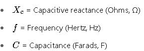
Capacitive reactance (Xc) is essential in AC analysis, power factor correction, and filter applications.
This guide offers formulas, tables, and examples to help calculate Xc accurately in real scenarios.
Capacitive Reactance Calculator (Xc)
Common Capacitive Reactance (Xc) Values Table
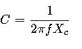
Capacitive reactance is calculated using the formula:
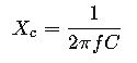
Where:
Below is a table of capacitive reactance values for commonly used capacitance values at standard frequencies (50 Hz, 60 Hz, 400 Hz):
Table 1: Capacitive Reactance (Ohms) at Different Frequencies
| Capacitance (µF) | Xc @ 50 Hz (Ω) | Xc @ 60 Hz (Ω) | Xc @ 400 Hz (Ω) |
|---|---|---|---|
| 0.01 | 318.3 | 265.3 | 39.8 |
| 0.1 | 31.83 | 26.53 | 3.98 |
| 1 | 3.183 | 2.653 | 0.398 |
| 10 | 0.3183 | 0.2653 | 0.0398 |
| 22 | 0.1447 | 0.1206 | 0.0179 |
| 47 | 0.0677 | 0.0564 | 0.0084 |
| 100 | 0.0318 | 0.0265 | 0.0040 |
| 220 | 0.0145 | 0.0121 | 0.0018 |
| 470 | 0.0068 | 0.0056 | 0.0008 |
| 1000 | 0.0032 | 0.0027 | 0.0004 |
Tip: Lower capacitance or higher frequency results in higher reactance. Large capacitors at low frequencies behave almost like short circuits.
Essential Formulas for Capacitive Reactance
Main Formula
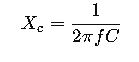
Where:
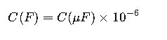
To convert microfarads (µF) to farads:
To isolate capacitance:
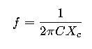
To isolate frequency:
These formulas are crucial in applications such as:
- Tuning circuits (e.g., radios, oscillators)
- Power factor correction
- AC filter design (low-pass, high-pass, etc.)
- Impedance matching in transmission lines
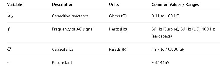
Variable Explanation and Common Values
Real-World Application Example 1: Power Factor Correction in Industrial Facility
Scenario:
An industrial motor operates at 60 Hz and draws inductive current causing a low power factor. To improve it, engineers install a capacitor bank. The goal is to design the correct capacitor size so that its capacitive reactance cancels part of the inductive reactance.
Given:
- Operating frequency f=60 Hzf
- Desired capacitive reactance Xc=10 Ω
Step-by-Step Solution:
Use formula:
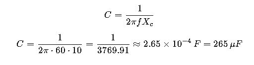
Result:
A 265 µF capacitor is required to provide 10 Ω of capacitive reactance at 60 Hz.
Application:
This method is used in:
- HVAC systems
- Factory automation motors
- Variable frequency drives (VFDs)
Real-World Application Example 2: Filter Design in Audio Electronics
Scenario:
You are designing a high-pass filter for an audio crossover system operating at 400 Hz, and the target is to block frequencies below that.
Given:
- Capacitance C=0.1 μF=0.1×10⁻⁶ F
- Frequency f=400 Hz
Step-by-Step Calculation:
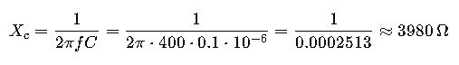
Result:
The reactance of this capacitor at 400 Hz is approximately 3.98 kΩ, which is suitable for filtering low-frequency signals in audio systems.
Application:
Used in:
- Speaker crossovers
- Instrument amplifiers
- Audio signal processing circuits
Extended Reference Table: Capacitive Reactance vs. Frequency and Capacitance
Below is a detailed matrix that shows how capacitive reactance XcX_cXc varies with both frequency and capacitance. This is critical for circuit design engineers working across different systems:
Table 2: Extended Xc Table (Ohms)
| Cap (µF) ↓ / Freq → | 10 Hz | 50 Hz | 60 Hz | 100 Hz | 400 Hz | 1 kHz | 10 kHz |
|---|---|---|---|---|---|---|---|
| 0.001 | 15.9 kΩ | 3.18 kΩ | 2.65 kΩ | 1.59 kΩ | 398 Ω | 159 Ω | 15.9 Ω |
| 0.01 | 1.59 kΩ | 318 Ω | 265 Ω | 159 Ω | 39.8 Ω | 15.9 Ω | 1.59 Ω |
| 0.1 | 159 Ω | 31.8 Ω | 26.5 Ω | 15.9 Ω | 3.98 Ω | 1.59 Ω | 0.159 Ω |
| 1 | 15.9 Ω | 3.18 Ω | 2.65 Ω | 1.59 Ω | 0.398 Ω | 0.159 Ω | 0.0159 Ω |
| 10 | 1.59 Ω | 0.318 Ω | 0.265 Ω | 0.159 Ω | 0.0398 Ω | 0.0159 Ω | 0.00159 Ω |
Note: These values are ideal; real-world capacitors may deviate slightly due to parasitic inductance and ESR (Equivalent Series Resistance).
Use of Capacitive Reactance in Engineering Fields
Understanding how capacitive reactance works is critical in numerous engineering disciplines:
1. Power Systems
- Power factor correction in substations and motors.
- Tuned filters to eliminate harmonics.
- Reactive compensation in transmission lines.
2. Telecommunications
- Coupling/decoupling capacitors based on frequency behavior.
- Impedance matching in RF and antenna circuits.
3. Audio Engineering
- Equalizers, crossover networks, high-pass/low-pass filters based on Xc tuning.
4. Aerospace & Avionics
- Critical filtering in 400 Hz AC systems.
- Lightweight, frequency-specific capacitive loading in avionics.
Capacitive Reactance vs Inductive Reactance
Understanding how capacitive reactance (Xc) interacts with inductive reactance (Xl = 2πfL) is essential in resonant circuits and reactive power management.
Table 3: Comparison Overview
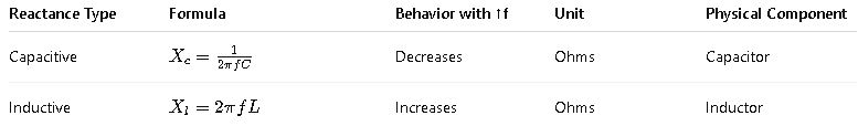
In series RLC circuits, resonance occurs when Xc=Xl, making the net reactance zero and maximizing current flow.
Normative and Practical Considerations
Capacitive reactance calculators must align with relevant standards and safety considerations:
Referenced Standards:
- IEEE Std 1036 – Guide for Application of Shunt Power Capacitors
- IEC 60143-1 – Series capacitors for power systems
- NFPA 70 / NEC – Wiring practices involving capacitive loads
- MIL-STD-202 – Capacitor reactance testing for military applications
Safety Tips:
- Never apply DC rated capacitors in AC circuits.
- Derate capacitors by 30–50% for voltage transients.
- Use ESR and ripple current ratings to evaluate real-world suitability.
External Tools and References
To further explore or simulate capacitive reactance scenarios, refer to these authoritative resources:
- IEEE Xplore: Capacitive Reactance Research
- All About Circuits – Reactance Basics
- Falstad Circuit Simulator – Real-time visual simulation
- Electronics Tutorials – Xc Calculator
Key Takeaways
- Capacitive reactance decreases with higher frequency or higher capacitance.
- It is a crucial parameter for designing AC circuits, filters, and reactive power systems.
- Use the formula
 for direct calculation or implement automated calculators.
 - Consider real-world capacitor limitations like ESR, temperature coefficients, and tolerance.
- Capacitive reactance directly impacts resonance, filtering, phase shift, and power quality.