Calculating short-circuit currents in electrical systems ensures safety, reliability, and proper operation of power installations. It determines the maximum fault current, crucial for selecting protective devices and designing fault-tolerant systems.
Short Circuit Current Calculator (Isc)
Which PF to use if unknown?
Voltage selection (L–N vs L–L)?
Formulas used
Three-phase AC: I = (1000·S)/(√3·V·PF)
DC: I = (1000·S)/V
Short-Circuit Current Calculation Formulas
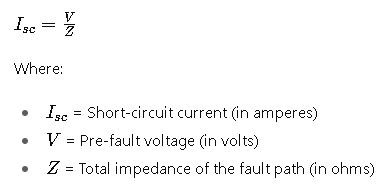
1. General Formula for Short-Circuit Current
The general formula to calculate the short-circuit current Isc is:

2. Single-Phase Faults
For single-phase faults, the impedance Z includes the series resistance and reactance of the fault path. The formula remains the same, but the impedance is calculated based on the specific fault path.
3. Three-Phase Faults
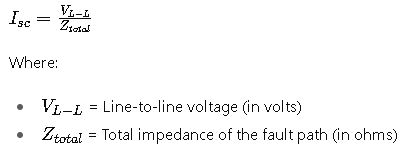
For three-phase faults, the short-circuit current is usually higher due to the combined contribution of all three phases. The formula is adjusted for three-phase systems:

In a three-phase system, the fault current is higher because all three phases contribute.
4. Transformer Fault Current Calculation
For transformers, the short-circuit current can be calculated using the transformer’s impedance and the system voltage:

This calculation is essential for determining the transformer’s contribution to the system’s short-circuit current.
Common Impedance Values for Short-Circuit Calculations
| Equipment Type | Impedance (Z) | Notes |
|---|---|---|
| Copper Conductor (1 km) | 0.028 Ω | Typical value for 1 km of copper conductor |
| Aluminum Conductor (1 km) | 0.045 Ω | Typical value for 1 km of aluminum conductor |
| Transformer (10 MVA) | 0.05 Ω | Impedance at full load |
| Generator (5 MVA) | 0.02 Ω | Impedance at full load |
| Busbar (1000 A) | 0.01 Ω | Typical busbar impedance |
These values are approximate and can vary depending on equipment ratings and system conditions.
Detailed Example Calculations
Example 1: Single-Phase Fault Calculation
Given:
- Pre-fault voltage V=230 V
- Total impedance Z=0.5 Ω
Calculation:
This means that during a single-phase fault, a current of 460 A would flow through the fault path.
Example 2: Three-Phase Fault Calculation
Given:
- Line-to-line voltage VL−L=400 V
- Total impedance Ztotal=0.2 Ω
Calculation:
During a three-phase fault, a current of 2000 A would flow through the fault path.
Real-World Application Scenarios
Scenario 1: Industrial Power Plant
In an industrial power plant, a three-phase short circuit occurs at the output of a 10 MVA transformer.
The transformer has an impedance of 0.05 Ω and the system operates at 11 kV line-to-line.
Calculation:
This high fault current requires circuit breakers with a high interrupting capacity to safely clear the fault.
Scenario 2: Residential Distribution System
In a residential distribution system, a single-phase fault occurs at the end of a 1 km copper conductor with a total impedance of 0.5 Ω.
The system operates at a phase voltage of 230 V.
Calculation:
This fault current is within the interrupting capacity of typical residential circuit breakers, ensuring safe operation.
Standards and References
- IEC 60909: Short-circuit currents in three-phase AC systems
- IEEE Std 141: IEEE Green Book – Electric Power Distribution
- IEEE Std 242: IEEE Buff Book – Protection and Coordination
These standards provide detailed methodologies for performing short-circuit calculations and ensuring system protection.
Tools and Software for Short-Circuit Calculations
Several software tools help engineers perform accurate short-circuit calculations:
- EasyPower: Complete short-circuit analysis capabilities according to IEC 60909.
- ETAP: Advanced modeling and simulation of power systems, including fault analysis.
- SKM PowerTools: Robust solutions for short-circuit and coordination studies.
These tools facilitate efficient and precise short-circuit analysis, aiding in the design and protection of electrical systems.


