This article explains NEC 220 load calculations for 14 AWG receptacles and show window demand.
Includes a free calculator workflow, formulas, examples, tables, and references for code-compliant instantaneous demand calculations.
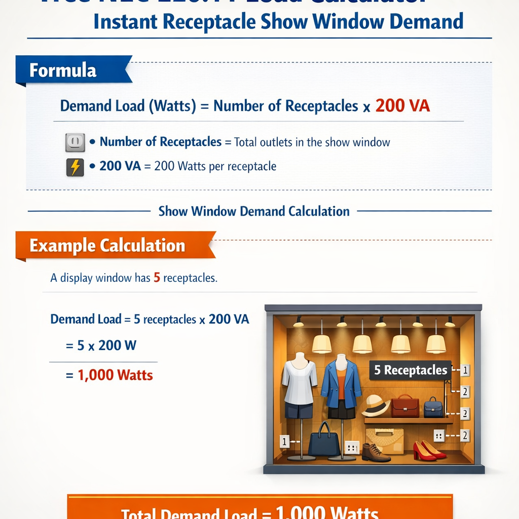
NEC 220.14 Receptacle and Show-Window Demand Load Calculator (VA and A)
- General-purpose receptacle load (VA) = Number of general-purpose outlets × VA per general-purpose receptacle.
- Show-window receptacle load by outlets (VA) = Number of show-window outlets × VA per show-window receptacle.
- Show-window load by length (VA) = Show-window length × VA per meter of show window (if both length and unit VA are provided).
- Show-window demand load (VA) = Greater of:
- Show-window receptacle load by outlets, and
- Show-window load by length (when both are specified).
- Base receptacle load (VA) = General-purpose receptacle load + Show-window demand load + Additional receptacle load.
- Demand-adjusted load (VA) = Base receptacle load × (Demand factor / 100).
- Continuous-adjusted design load (VA) = Demand-adjusted load × Continuous load factor.
- Branch-circuit current (A) = Continuous-adjusted design load (VA) ÷ Branch-circuit voltage (V).
- Approximate feeder current, single-phase (A) = Design load (VA) ÷ Feeder line-to-line voltage (V).
- Approximate feeder current, three-phase (A) = Design load (VA) ÷ (√3 × Feeder line-to-line voltage (V)), with √3 ≈ 1.732.
| Application | Typical unit load (VA) | Notes |
|---|---|---|
| General-purpose receptacle outlet | 180 VA per strap | Commonly used for general receptacle outlets in commercial occupancies. |
| Show-window receptacle outlet | ≈ 660 VA per outlet | Representative value; confirm the exact requirement in the NEC edition in force. |
| Show-window length-based load | Several hundred VA per meter | NEC assigns a unit VA per unit length; this calculator lets you enter the value explicitly. |
| Continuous load factor | 125 % | Applied to continuous loads for conductor and OCPD sizing per NEC 210.20(A) and 215.3. |
How does this calculator apply NEC 220.14 to receptacle loads?
It assigns a unit load in volt-amperes to each receptacle outlet (typically 180 VA for general-purpose and around 660 VA for show-window outlets), optionally applies a length-based unit load for show windows, adds any additional receptacle VA, and then applies a demand factor and continuous-load factor. From the resulting design VA, it computes branch-circuit and optional feeder currents.
When should I use show-window length instead of only receptacle count?
Many NEC editions require show-window load to be calculated by both receptacle count and window length, then to use the larger of the two results. Use the length and VA-per-meter fields when the code specifies a unit load based on show-window length, and keep the receptacle count fields filled so that the calculator can select the worst case.
What value should I use for the demand factor?
If your jurisdiction does not provide a specific demand factor for receptacle loads, a conservative approach is to use 100%. Where local practice or other NEC tables justify diversity, you may use a lower demand factor (e.g., 80–100%) consistent with your design standards and authority having jurisdiction.
Does this tool replace a complete NEC load calculation?
No. This calculator focuses on receptacle and show-window loads per NEC 220.14. A full service or feeder calculation must include lighting, HVAC, fixed appliances, motors, and other loads, and must follow all applicable articles, tables, and local amendments.
Scope and Purpose
This document provides a technical approach to compute instantaneous and demand loads per NEC Article 220 for installations using 14 AWG (15 A) branch circuits. It focuses on receptacle loads, show-window lighting and display loads, and how to implement a free "instant calculator" algorithm that an engineer or designer can use to size conductors, overcurrent protection, and branch circuit counts.NEC 220 Essentials Relevant to Receptacles and Show Windows
General methodology from NEC Article 220
NEC Article 220 establishes methods to determine loads: identify all connected loads, classify as continuous or non-continuous, apply unit values and demand factors where permitted, and sum loads to determine minimum feeder and service requirements. For branch-circuit level design, the same identification and classification logic applies but with attention to conductor ampacity and branch-circuit overcurrent limits (NEC 240).Key NEC concepts applied here:- Unit loads for general-use receptacles (commonly used engineering values).
- Continuous load consideration: Size circuits for 125% of continuous current per NEC 210.19(A)(1) and 215.3 when applicable.
- Application of demand factors and specific tables where NEC provides allowances.
14 AWG conductor and protective-device limits
14 AWG copper conductors are typically protected at 15 A. NEC 240.4(D) restricts overcurrent devices to the conductor ampacity for small conductors. For continuous loads, branch circuits must be rated for 125% of the continuous current; for a 15 A overcurrent device the practical continuous ampacity becomes a limiting factor and may require multiple circuits.Unit Values and Typical Engineering Assumptions
The NEC often permits or requires the use of unit-load values for receptacles and specific demand factors for lighting and other loads. Many engineering practices and utility calculators use the unit values below for quick estimates. These are engineering defaults; always confirm with the latest NEC edition and local amendments.| Load Type | Typical Unit Value (VA) | NEC Note / Typical Use |
|---|---|---|
| General-use duplex receptacle (engineering default) | 180 VA per duplex | Commonly used for non-dwelling load estimations; practical engineering assumption. |
| Single receptacle (non-duplex) | 120 VA | Less common; used where single outlets are specified. |
| Small appliance branch circuit (kitchen) | 1500 VA per circuit (minimum) | NEC requires at least two small-appliance circuits in dwelling kitchens. |
| Show window lighting (typical retail accent lighting) | 500–2000 VA per window section (varies) | Highly variable; assign measured or manufacturer VA where available. |
| Continuous load multiplier | 1.25 (125%) | Used to size conductors and overcurrent devices for continuous loads. |
| Voltage for receptacles (typical US) | 120 V or 120/240 V | Voltage used to convert VA to amperes: I = VA / V. |
Formulas and Variable Definitions
Below are key formulas presented in plain HTML text. Each formula is followed by variable explanations and typical values.- P (VA) = Apparent power in volt-amperes.
- V (V) = Nominal voltage of circuit (typically 120 V for single-phase receptacles in the US).
- I (A) = Current in amperes.
- Typical value: A 120 V, 15 A circuit maximum theoretical VA = 120 × 15 = 1800 VA.
- Required ampacity (A) = Long-term (continuous) current × 125%.
- NEC clarification: Continuous means expected to run for 3 hours or more.
- Example: A 12 A continuous load requires conductor ampacity = 12 × 1.25 = 15 A.
- N_duplex = Number of duplex receptacles served by the calculation.
- 180 VA per duplex is an engineering default widely used in non-dwelling calculations.
- Adjust unit value if building-specific data or manufacturer ratings differ.
- Use nominal voltage: 120 V for single-phase receptacles.
- For multi-wire branch circuits or 240 V loads, use appropriate phase voltage.
NEC continuous-check for 14 AWG circuit: Max continuous current allowable without exceeding 80% rule on breaker = 15 A × 0.8 = 12 A
- Therefore continuous permissible VA on 120 V = 12 A × 120 V = 1440 VA.
- Design conservative: limit continuous branch-circuit load to 1440 VA for 14 AWG protected at 15 A.
Calculator Algorithm for Instant Receptacle and Show Window Demand
A free instant calculator implements these steps. The algorithm below can be coded into a lightweight web calculator or used manually.- Input circuit voltage (default 120 V), conductor size (default 14 AWG), breaker rating (default 15 A).
- List all receptacles by type (duplex, single) and assign unit VA values or measured VA for each connected load.
- List show window lighting and display loads in VA (use manufacturer ratings or measured consumption).
- Classify any loads as continuous or non-continuous. Apply continuous multiplier (×1.25) to continuous loads for conductor and OCPD sizing.
- Sum all VA to obtain total connected VA. Apply NEC demand factors where permitted (e.g., lighting demand factors, motor load reductions) — if no table applies, use full connected load.
- Convert total VA to amperes: I_total = Total VA / V.
- Compare I_total to allowable branch-circuit current. For 14 AWG on 15 A breaker the practical continuous limit = 12 A. If I_total > allowed, increase number of circuits or redistribute loads.
- Report: total VA, current, whether continuous criteria are met, number of branch circuits required, conductor size check, and recommendations.
Design Rules Specific to Show Windows and Display Lighting
Show windows often include accent lighting, track systems and other fixtures with high localized loads. Key points:- Treat show-window lighting as part of the lighting load category unless connected to dedicated circuits for display equipment; record manufacturer VA.
- Where show-window lighting is a constant display (on for long periods), classify as continuous and apply 125% sizing.
- If lighting is likely to be modified by store owners (re-lamping, adding fixtures), design for reasonable future expansion or provide spare circuits.
- Consider local code amendments: some jurisdictions require separate circuits or dedicated signage/load circuits for display windows.
Worked Example 1 — Retail Show Window on a 14 AWG 15 A Branch Circuit
Problem statement: A retail storefront has a show window with accent lighting and three duplex receptacles located in the display area. The accent lighting uses LED track heads with manufacturer rating 600 VA total. Each duplex receptacle is assumed 180 VA (engineering default). The owner wants these loads on a single 14 AWG branch circuit protected at 15 A. Determine if a single circuit is acceptable and compute currents, applying NEC continuous load rules if the lighting is continuously on.Step-by-step solution:- Assign values:
- Show window lighting = 600 VA (manufacturer rating).
- Three duplex receptacles: N_duplex = 3 → Receptacle VA = 3 × 180 = 540 VA.
- Total connected VA = 600 + 540 = 1140 VA.
- Classify continuous loads: Assume the show-window lighting is continuous (on for >3 hours). Receptacles are typically non-continuous unless loads are known continuous. Apply continuous multiplier to continuous portion only.
- Apply 125% to continuous lighting:
- Effective lighting VA for conductor sizing = 600 × 1.25 = 750 VA.
- Receptacle VA remains 540 VA (non-continuous assumed).
- Total adjusted VA for sizing = 750 + 540 = 1290 VA.
- Compute current on 120 V:
- I = Total VA / V = 1290 VA / 120 V = 10.75 A.
- Check against continuous allowable on 14 AWG protected at 15 A:
- Continuous rule: breaker must be 125% of continuous load; conversely conductor cannot be loaded above allowable continuous limit. Practical continuous limit for a 15 A breaker = 12 A (80% rule for breaker).
- Calculated continuous current = 10.75 A < 12 A → Acceptable on one 15 A/14 AWG circuit.
- Safety margin: The remaining headroom = 12 A − 10.75 A = 1.25 A (~150 VA). If future additions likely, consider separate circuit or larger conductor/breaker if allowed.
| Parameter | Value |
|---|---|
| Show window lighting (continuous) | 600 VA → adjusted 750 VA |
| Three duplex receptacles | 540 VA |
| Total adjusted VA | 1290 VA |
| Calculated current at 120 V | 10.75 A |
| Allowed continuous current on 14 AWG / 15 A breaker | 12 A |
| One-circuit feasible? | Yes, with ~1.25 A margin |
Worked Example 2 — Multiple Show Windows and Receptacles Exceeding Single Circuit Capacity
Problem statement: A larger storefront has two adjacent show windows, each with accent lighting rated 900 VA continuously and four duplex receptacles distributed across the display (total of 4 duplex). Determine required number of 14 AWG 15 A branch circuits, assuming continuous show lighting.Step-by-step solution:- Assign values:
- Show window A lighting = 900 VA (continuous).
- Show window B lighting = 900 VA (continuous).
- Four duplex receptacles: 4 × 180 VA = 720 VA (assume non-continuous unless specified).
- Adjust continuous portions by 125% for conductor sizing:
- Window A adjusted = 900 × 1.25 = 1125 VA.
- Window B adjusted = 900 × 1.25 = 1125 VA.
- Receptacles remain 720 VA.
- Total adjusted VA = 1125 + 1125 + 720 = 2970 VA.
- Compute total current on 120 V:
- I_total = 2970 VA / 120 V = 24.75 A.
- Determine number of 15 A branch circuits required, using allowable continuous limit per circuit = 12 A (1440 VA):
- VA per 14 AWG 15 A circuit (continuous limit) = 1440 VA.
- Number of circuits = ceil(Total adjusted VA / 1440) = ceil(2970 / 1440) = ceil(2.0625) = 3 circuits.
- Distribution strategy:
- Option A: Provide three 15 A/14 AWG branch circuits and distribute loads to keep each circuit ≤ 1440 VA continuous equivalent.
- Example distribution:
- Circuit 1: Window A adjusted 1125 VA + 1 duplex (180 VA) = 1305 VA.
- Circuit 2: Window B adjusted 1125 VA + 1 duplex (180 VA) = 1305 VA.
- Circuit 3: Remaining 2 duplex receptacles = 360 VA (non-continuous), leaving spare capacity for future expansion.
| Parameter | Value |
|---|---|
| Total continuous adjusted VA | 2970 VA |
| Continuous VA capacity per 14 AWG/15 A circuit | 1440 VA |
| Minimum required 15 A circuits | 3 circuits |
| Example distribution leaves spare capacity on Circuit 3 | Yes |
Tables of Common Values and Conductor Limits
Below are extended reference tables frequently used during instant calculations. These tables consolidate conductor limits, continuous-load rules, and common receptacle assumptions.| Conductor Size (AWG) | Typical Allowed Overcurrent Device (A) | Continuous Limit (80% of OCPD) (A) | Continuous VA at 120 V (VA) |
|---|---|---|---|
| 14 AWG Cu | 15 A | 12 A | 1440 VA |
| 12 AWG Cu | 20 A | 16 A | 1920 VA |
| 10 AWG Cu | 30 A | 24 A | 2880 VA |
| 8 AWG Cu | 40 A | 32 A | 3840 VA |
| 6 AWG Cu | 60 A | 48 A | 5760 VA |
| Load Item | Typical Unit VA | Comment |
|---|---|---|
| General duplex receptacle | 180 VA | Engineering default for non-dwelling |
| Single receptacle | 120 VA | Where single outlet specified |
| Small-appliance circuit (dwelling) | 1500 VA per required circuit | NEC requirement for dwelling kitchens |
| Show window accent lighting | Measured VA or 500–2000 VA | High variability; use manufacturer data |
| Emergency lighting | Manufacturer VA | Often requires separate emergency supply |
Practical Design Guidance and Best Practices
- Prefer measured or nameplate VA for fixtures over assumptions where possible.
- When show-window lighting is continuous, always apply 125% for conductor sizing and ensure branch-circuit capacity meets the continuous requirement.
- Account for future changes: retail displays change often; provide spare circuits or higher capacity when justified by cost-benefit analysis.
- Document assumptions and calculation worksheets and reference the exact NEC edition and local amendments used.
- For multi-wire branch circuits or 240 V loads, convert VA using proper phase relationships and power-factor where applicable: I = VA / V_phase.
Implementation Notes for a Free Instant Calculator Tool
When implementing a free online or spreadsheet-based NEC 220 instant calculator for 14 AWG circuits, follow these recommendations:- Input validation: ensure user enters VA or watts for each item, distinguishes continuous vs non-continuous loads, and selects nominal voltage.
- Default unit values: provide defaults (e.g., 180 VA per duplex) with clear labels that they are engineering defaults, not code-mandated values.
- Continuous handling: automatically apply 1.25 multiplier to continuous loads for conductor sizing display, and also display connected vs adjusted loads separately.
- Breakdown output: show connected VA, adjusted VA, calculated current, allowed continuous current per conductor size, and recommended number of circuits.
- Exportable documentation: enable export of calculation summary to PDF or spreadsheet for plan submittal and inspection records.
Normative References and Authoritative Links
The following references should be consulted for regulatory compliance and detailed code language. Always verify the edition of the NEC or local code adopted by the authority having jurisdiction (AHJ).- NFPA 70, National Electrical Code — official source and handbook: https://www.nfpa.org/NEC
- NFPA 70 Article 220 — Branch-circuit, feeder, and service calculations (consult current NEC text for specific tables): https://www.nfpa.org
- NEC Handbook and commentary for interpretation of unit loads and demand factors (subscription or purchase may be required): https://www.nfpa.org/NEC
- IEEE Standards and guidance on electrical design and power calculations: https://www.ieee.org
- US Government energy efficiency and lighting data (useful for measured lighting loads): https://www.energy.gov/
- Manufacturer datasheets for fixtures and loads — always use nameplate or datasheet VA for exact load values.
Regulatory and Safety Notes
- This article provides engineering guidance and examples intended for design-level estimation. It does not replace the NEC text or AHJ direction.
- Always verify local amendments to the NEC; jurisdictions may have specific requirements for show-window circuits or receptacle counts.
- Do not oversize conductors or overcurrent devices contrary to NEC 240.4(D) for small conductors; for increased ampacity, select the proper conductor size and follow NEC ampacity tables.
- Label circuits and provide documentation for maintenance staff to prevent unauthorized changes that might overload branch circuits.
Appendix — Quick Reference Calculation Examples
| Scenario | Connected VA | Adjusted VA (with continuous) | Calculated Current (A) | Circuits Required (14 AWG/15 A) |
|---|---|---|---|---|
| One window 600 VA + 3 duplex | 1140 VA | 1290 VA | 10.75 A | 1 |
| Two windows 900 VA each + 4 duplex | 2520 VA | 2970 VA | 24.75 A | 3 |
| Single duplex only | 180 VA | 180 VA | 1.5 A | 1 |
| Heavy display 2000 VA continuous | 2000 VA | 2500 VA | 20.83 A | 2+ |
Recommended Checklist for Field Verification
- Measure actual fixture VA with a power meter when possible.
- Document which loads are truly continuous (≥3 hours) and label circuits accordingly.
- Confirm conductor sizes and breaker ratings match plan and field conditions.
- Verify load distribution and whether any multi-wire branch circuits require handle-tied breakers or common trip as per NEC.
- Coordinate with AHJ for acceptable unit values and any required load diversity factors for retail/show-window applications.
Final Remarks
This technical article defines a practical, code-aware process to calculate instantaneous and demand loads for 14 AWG branch circuits serving receptacles and show-window lighting. Use manufacturer data where available, apply NEC continuous-load multipliers for any loads expected to run three hours or more, and ensure that calculated currents do not exceed the practical continuous limit for 14 AWG on a 15 A breaker (12 A). When totals exceed a single circuit capacity, distribute loads across additional circuits following NEC rules and AHJ requirements.References above point to authoritative documents; always cross-check with the specific NEC edition and local code authority before final design or installation.