This article explains parallel service conductor calculation methods for determining conductor sets and sizes accurately.
Focused technical guidance covers derating factors, NEC rules, formulas, examples, and practical selection procedures recommended.Parallel Service Conductors Calculator – Number of Sets for a Given Conductor Size
Scope, purpose and practical outcomes
This document provides a rigorous workflow to calculate how many parallel service conductor sets are required given a known load, conductor type, and installation conditions. It is intended for electrical engineers, designers, and qualified electricians responsible for service and feeder sizing under modern codes and industry best practices.
Regulatory framework and key requirements
Parallel conductors are governed by national electrical codes and manufacturer ratings. In the United States, the National Electrical Code (NEC) contains specific rules on conductor ampacity, derating for multiple current-carrying conductors, and parallel conductor requirements. Confirm applicable local amendments and the authority having jurisdiction (AHJ).
- NEC requirement: parallel conductors are permitted only for conductors of equal length, material, size, insulation type, and termination ratings. See NEC 310.10(H) (or the applicable edition).
- Continuous loads: design ampacity must account for continuous loads (typically using 125% multiplier where required by NEC 210.19(A)(1) / 215.2(A)(1)).
- Derating: apply adjustment factors for more than three current-carrying conductors in a raceway or cable assembly (NEC 310.15(B)(3)(a) or current edition equivalent).
General calculation methodology (step-by-step)
Follow the sequence below to compute the number of parallel sets required for a service or feeder circuit:
- Define the full load current (FLA) or service load (in amperes) based on equipment nameplate, load study, or design basis.
- Separate continuous and non-continuous portions of the load. Multiply continuous portions by 125% per NEC where applicable to determine Required Ampacity (RA).
- Select candidate conductor material and insulation (copper/aluminum, temperature rating such as 75°C or 90°C). Obtain base ampacity from manufacturer tables or NEC ampacity tables.
- Identify number of current-carrying conductors in the raceway/cable so you can apply adjustment (grouping) factors. Apply the appropriate adjustment factor to the base ampacity to compute Adjusted Ampacity (AA).
- Apply temperature correction factor if ambient or conductor temperature rating differs from the standard ampacity column used.
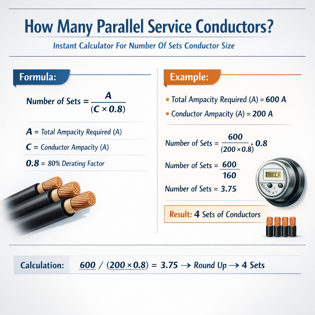
- Compute the number of conductors (sets) required: divide Required Ampacity by Adjusted Ampacity per conductor and round up to the next whole number, then convert to sets (each set normally includes the required phase conductors; for single-phase service with two conductors per phase a 'set' may be two parallel conductors per phase, etc.).
- Confirm that the chosen conductor size meets parallel conductor rules (minimum size for parallel use) and that termination lugs or bus ratings accept parallel conductors.
Key formulas and variable definitions
Variables:
- Continuous_Load — current (A) of loads classified as continuous (≥3 hours).
- NonContinuous_Load — current (A) of non-continuous loads.
Variables:
- Base_Ampacity — tabulated ampacity for the conductor at the selected conductor temperature rating (A).
- Grouping_Factor — derating factor for number of current-carrying conductors (decimal, e.g., 0.80 for 80%).
- Temperature_Factor — correction factor for ambient temperature or termination rating (decimal).
Variables:
- RA — Required_Ampacity calculated above (A).
- AA — Adjusted_Ampacity_per_Conductor (A).
- ceil() — mathematical ceiling function (round up to nearest integer).
Derating and adjustment factors (grouping and temperature)
Accurate calculation requires sequential application of derating factors: first apply grouping (more-than-three conductors) then apply ambient-temperature/termination correction. Order matters because the product yields final available ampacity.
| Number of current-carrying conductors in raceway/cable | Grouping (Adjustment) factor |
|---|---|
| 1, 2, or 3 | 1.00 (no adjustment) |
| 4–6 | 0.80 |
| 7–9 | 0.70 |
| 10–20 | 0.50 |
| 21–30 | 0.45 |
| 31–40 | 0.40 |
| 41–50 | 0.35 |
| >50 | 0.30 |
Ambient temperature correction factors depend on conductor insulation and the column of the ampacity table used (e.g., 60°C, 75°C, 90°C). Typical temperature correction factors (sample values — consult latest NEC table or manufacturer data):
- For THHN (90°C column) at 30°C ambient: factor ≈ 1.00 (no correction).
- For THHN at 40°C ambient: factor ≈ 0.91.
- For THHN at 50°C ambient: factor ≈ 0.82.
Note: Always use the temperature column permitted by the terminal rating (e.g., if terminals rated 75°C, use the 75°C ampacity column and applicable temperature factors).
Representative ampacity table (typical values for design reference)
Below are representative ampacity values commonly used in preliminary design. These numbers are for typical copper (Cu) and aluminum (Al) conductors, and are examples only — always verify with the NEC table and manufacturer data for your installation and terminal temperature rating.
| Conductor (AWG / kcmil) | Copper Ampacity (75°C) [A] (typical] | Aluminum Ampacity (75°C) [A] (typical] |
|---|---|---|
| 4 AWG | 95 | 65 |
| 3 AWG | 115 | 80 |
| 2 AWG | 130 | 95 |
| 1 AWG | 150 | 110 |
| 1/0 AWG | 170 | 125 |
| 2/0 AWG | 195 | 145 |
| 3/0 AWG | 225 | 165 |
| 4/0 AWG | 260 | 195 |
| 250 kcmil | 285 | 215 |
| 350 kcmil | 335 | 260 |
| 500 kcmil | 380 | 320 |
| 750 kcmil | 455 | 415 |
Important: These values are illustrative. Use the specific NEC edition ampacity table (e.g., NEC 310.16 / 310.15(B)(16) or local equivalent) and the conductor manufacturer's data for final calculations.
Parallel conductor rules and practical constraints
Parallel conductor installations impose specific constraints beyond ampacity arithmetic. Key points to verify:
- Minimum size for parallel: per NEC, most editions require conductors to be 1/0 AWG or larger to be paralleled — confirm the exact clause in the edition you use.
- Conductor equality: same material, same size, same insulation type, same number of strands, same manufacturer if possible.
- Termination and bus ratings: terminals and lugs must be listed to accept multiple parallel conductors and rated for their combined cross-sectional area; check manufacturer's instructions.
- Equal length: for balanced current sharing, each parallel conductor must have practically equal length and routing to minimize impedance mismatch.
- Mechanical fastening and identification: clearly mark parallel conductors and secure them per installation practice to maintain equal spacing and heat dissipation.
Worked example 1 — Copper service: 400 A continuous load
Problem statement: A commercial service supplies a continuous design load of 400 A (all continuous). You will select copper conductors and determine how many parallel conductor sets per phase are required. Installation uses THHN insulation in conduit with ambient temperature 30°C. Termination lugs are rated 75°C.
Step 1 — Required Ampacity (RA): Because the entire load is continuous, apply 125% multiplier.
Step 2 — Candidate conductor selection: choose 3/0 AWG copper (common choice). Use typical 75°C base ampacity for 3/0 Cu from reference table = 225 A (typical).
Step 3 — Count current-carrying conductors in each conduit: assume one set per phase initially, so for three-phase, if only one conductor per phase inside the conduit there are 3 current-carrying conductors (no adjustment required). If neutrals carry current, count them as current-carrying where they carry unbalanced or harmonic currents — for balanced three-phase with solidly grounded neutral carrying negligible current, the neutral may not be counted. For this example, assume only three phase conductors per conduit and neutral is outside or not carrying continuous current, so grouping factor = 1.00.
Step 4 — Temperature correction: ambient 30°C and terminations rated 75°C, use 75°C ampacity column; temperature factor = 1.00 for typical conditions.
Result: Use three 3/0 Cu conductors in parallel per phase (three parallel conductors per phase). That results in an effective ampacity per phase of 3 × 225 A = 675 A (subject to final verification). This selection satisfies RA = 500 A.
Verification of code constraints: 3/0 AWG is larger than 1/0 so parallel is permitted; ensure conductors are equal length and that terminations accept three parallel conductors or use bussing/lugs listed for parallel conductor termination. If lugs do not accommodate multiple conductors, use parallel bus bars or listed splices inside properly rated enclosures.
Worked example 2 — Aluminum service: 600 A mixed continuous/non-continuous
Problem statement: A service supplies a combined load of 600 A, where 450 A is continuous and 150 A is non-continuous. Aluminum conductors are preferred due to cost. The installation uses 500 kcmil AL conductors with typical 75°C ampacity (illustrative) = 320 A. There will be two parallel conductors per phase initially planned. Raceways contain only three phase conductors plus a neutral located separately; grouping factor = 1.00. Ambient is 30°C and terminations rated 75°C.
Step 1 — Required Ampacity (RA): apply 125% to continuous portion and add non-continuous portion.
Step 2 — Base ampacity and adjustments: Base_Ampacity per 500 kcmil Al (75°C) = 320 A (typical). Grouping factor = 1.00; temperature factor = 1.00.
Step 4 — Calculate number of parallel conductors required:
Interpretation: You need three parallel 500 kcmil aluminum conductors per phase to achieve the required ampacity. Two parallel conductors (2 × 320 A = 640 A) would be insufficient because 640 A < 712.5 A. Three parallels give 960 A capacity (subject to confirmation).
Code check: Ensure 500 kcmil AL is permitted to be paralleled, that all conductors are same length and type, and that the equipment terminations accept the parallel conductors or that listed splices/terminations are provided.
Additional practical considerations and common pitfalls
- Always size conductors based on the terminal temperature rating, not only the conductor insulation rating; this often limits the ampacity column (commonly 75°C).
- Remember to include derating for ambient temperature if conductors are in direct sunlight, in duct banks, or in high ambient environments (multiply by manufacturer-supplied temperature correction factors).
- Counting current-carrying conductors: neutrals carrying only imbalance currents may not be counted, but neutrals carrying harmonic currents or in systems with nonlinear loads may be treated differently. Consult code language and engineering judgment.
- Unexpected grouping: multiple circuits pulled in the same conduit can force aggressive derating; consider separate raceways or using larger conductors to avoid excessive derating.
- Ensure mechanical feasibility: large numbers of parallel conductors increase conductor bundle area, bend radii, and require larger troughs or transformerlug space.
Implementation checklist before installation
- Verify load calculations and identify continuous load portions.
- Select conductor material, size and insulation consistent with load and termination temperature rating.
- Apply grouping and temperature correction factors sequentially to compute final adjusted ampacity.
- Compute number of parallel conductors and confirm minimum size for paralleled conductors per code.
- Confirm termination and lug compatibility with parallel conductors or plan for listed splices/bussings.
- Document conductor routing, lengths and balancing strategy; mark and tag conductors and provide installation drawings.
- Obtain AHJ approval where required and include references to the code edition used in the documentation.
Useful normative references and authoritative external resources
- NFPA 70, National Electrical Code (NEC). Official source: https://www.nfpa.org/nec — consult the edition adopted by your jurisdiction.
- NEC commentary and ampacity tables — review NEC Article 310 (conductors, ampacity) and Article 310.10(H) on parallel conductors.
- IEEE standards relevant to power cable sizing and installation practices: https://standards.ieee.org/
- IEC 60228 — Conductors of insulated cables (for international conductor class definitions): https://www.iec.ch/
- Manufacturer ampacity and installation guides (e.g., Prysmian, Southwire, Belden) — use manufacturer data for final verification.
- Technical guidance on derating and grouping: industry articles and engineering handbooks (e.g., IEEE/NEC handbooks).
References cited
- NEC Article 310 — Conductors for general wiring and ampacity rules (see current edition for exact clause numbering and tables).
- NEC 310.10(H) — requirements for parallel conductors (verify edition-specific language).
- NEC 210.19(A)(1) and 215.2(A)(1) — sizing for branch-circuits and feeders regarding continuous loads (apply 125% where required).
Summary of procedural algorithm for an "instant calculator"
If you implement an instant calculator (spreadsheet, script, or web tool) follow this algorithm:
- Input: Total phase current; continuous current portion; conductor material; chosen conductor size(s); number of current-carrying conductors in the conduit; ambient temperature; terminal temperature rating.
- Compute Required_Ampacity as continuous portion × 1.25 + non-continuous portion.
- Lookup Base_Ampacity for selected conductor at the terminal temperature column.
- Apply Grouping_Factor based on current-carrying conductor count.
- Apply Temperature_Factor for ambient vs table conditions.
- Compute Adjusted_Ampacity AA = Base_Ampacity × Grouping_Factor × Temperature_Factor.
- Compute Number_of_conductors N = ceil( RA / AA ).
- Validate: N must produce conductor size >= minimum parallel size threshold; if not, select larger conductor size or increase N accordingly.
- Output: N per phase, notes on code constraints and recommended verification steps.
Closing technical recommendations
When deploying parallel conductors for services and feeders, prioritize safety, code compliance, and maintainability: select conductor sizes that minimize the number of parallels while meeting mechanical and termination constraints. Always verify with the latest code edition, manufacturer data, and AHJ interpretation.
Further reading and tools
- NEC Handbook commentary for ampacity and conductor installation examples (purchase or institutional access).
- Manufacturer ampacity tables and correction factor charts for specific insulation systems.
- Engineering calculators from reputable sources (university or industry) — ensure they reference the correct code edition and table sources.
If you want, I can generate a spreadsheet-ready calculation table or a step-by-step spreadsheet template implementing the algorithm above with configurable inputs and automatic grouping/temperature corrections.