This guide provides essential steps for selecting transformer sizing with affordability and code compliance safely.
Practical calculations, constraints, and examples help engineers balance load growth, losses, and cost over time.
Transformer Sizing Calculator — Practical & Affordable Guide
Transformer sizing fundamentals and objectives
Transformer sizing requires balancing electrical demand, economic constraints, and regulatory requirements. The primary engineering objectives:- Ensure continuous load capacity without thermal overload.
- Provide adequate short‑circuit withstand and protection coordination.
- Minimize life‑cycle cost through optimal losses and efficiency.
- Accommodate motor starting, harmonics, and future load growth.
Key planning metrics
The essential metrics used in transformer selection are:- Rated kVA (apparent power capacity)
- Primary and secondary voltage levels
- Load power factor (PF)
- Maximum expected continuous kW and peak inrush currents
- Impedance (%Z) and short‑circuit current capability
- Temperature rise class, ambient temperature, and cooling method (ONAN, ONAF)
Load assessment and classification
Accurate load assessment is mandatory. Loads are categorized by their duty cycles and composition:- Continuous loads (operate > 3 hours): size transformer to handle continuous rating.
- Non‑continuous loads (intermittent): evaluate diversity and simultaneity factors.
- Motor loads: consider locked‑rotor current and inrush multipliers.
- Nonlinear loads: assess harmonic content, derating for heating and neutral currents.
Data collection checklist
Collect:- List of connected loads with kW or kVA and PF.
- Load duty cycles and diversity estimates.
- Starting characteristics of motors (HP, service factor, full load current, locked rotor current).
- Voltage levels and available short‑circuit MVA upstream.
- Ambient temperature, altitude, and enclosure constraints.
Primary formulas for sizing
Use clear algebraic expressions to compute transformer kVA, currents, and required impedance.Apparent power and current
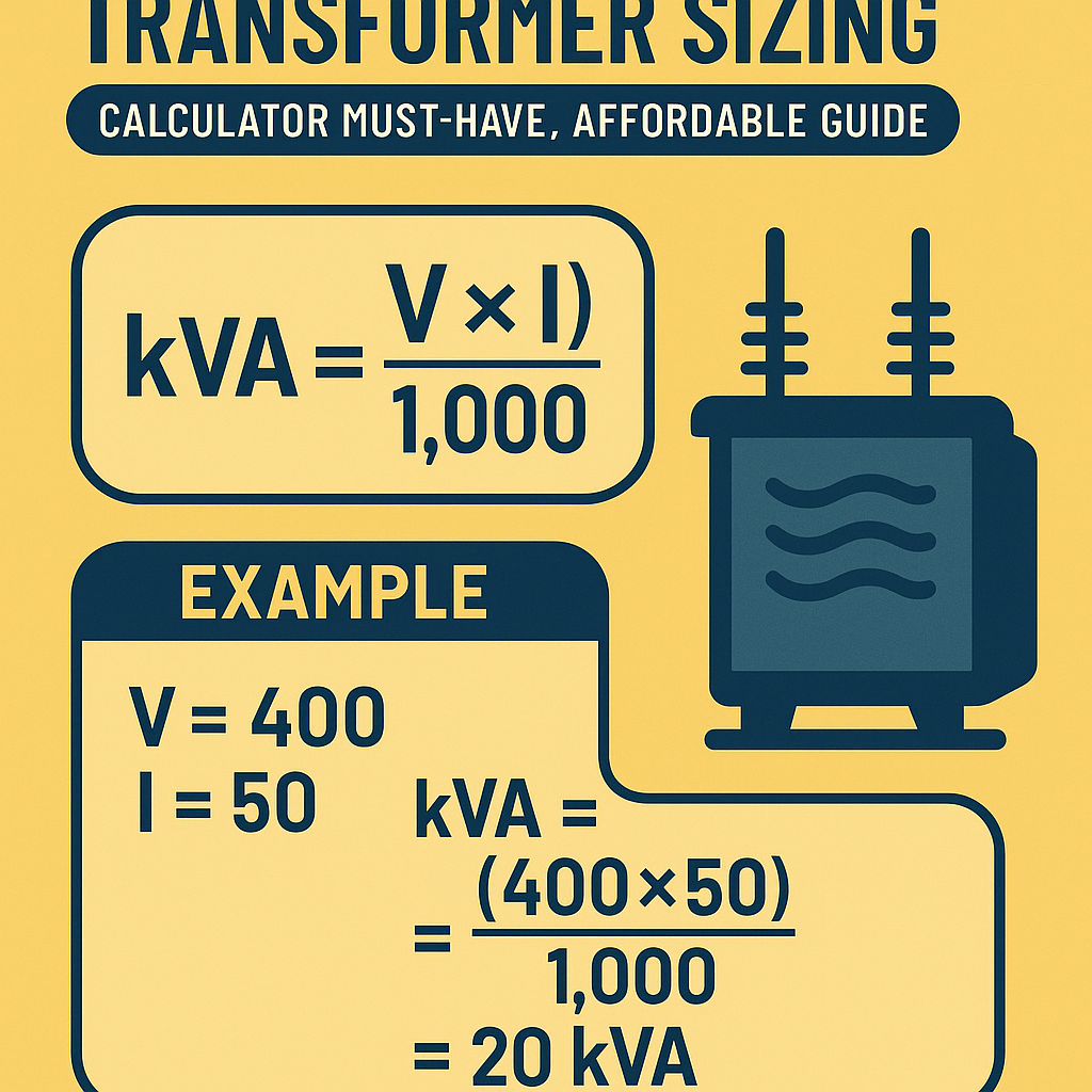
For three‑phase systems: Sizing_kVA = (Load_kW × 1000) ÷ (√3 × V_line × PF)For single‑phase systems: Sizing_kVA = (Load_kW × 1000) ÷ (V × PF)Explained variables and typical values:- Sizing_kVA: transformer rated capacity in kilovolt‑amperes (kVA).
- Load_kW: real power demand in kilowatts (kW). Typical: residential 0.5–10 kW per dwelling, light commercial 10–100 kW, industrial >100 kW.
- √3: square root of three (≈1.732) for three‑phase conversions.
- V_line: line voltage (three‑phase), common values 208 V, 400 V, 480 V, 600 V, 11 kV, 33 kV.
- V: single‑phase voltage, common values 120 V, 240 V, 277 V.
- PF: power factor, typical 0.8–0.95. For resistive loads PF ≈1, for motors PF ≈0.8 lagging.
Full load current from kVA
Three‑phase full load current: I_FL = (Sizing_kVA × 1000) ÷ (√3 × V_line)Single‑phase full load current: I_FL = (Sizing_kVA × 1000) ÷ VExplained variables:- I_FL: full load current (A).
- Sizing_kVA: chosen transformer rating (kVA).
- V_line or V: system voltage (V).
Transformer impedance and short‑circuit current
Percent impedance relation: I_sc_primary = (Transformer_kVA ÷ %Z) × (100 ÷ Base_current)A common practical calculation for available short‑circuit current on secondary side: I_sc_secondary = (Transformer_kVA × 1000) ÷ (√3 × V_secondary × (%Z ÷ 100))Variables and typical values:- %Z: percentage impedance, typical range 2.5%–8% for distribution transformers.
- Transformer_kVA: rated kVA.
- V_secondary: secondary line voltage.
Standard transformer ratings and selection tables
Manufacturers provide standardized kVA steps. Use the tables below to shortlist candidate units, then apply thermal and short‑circuit checks.| Standard kVA | Three‑phase full load current @ 480 V (A) | Three‑phase full load current @ 400 V (A) | Three‑phase full load current @ 208 V (A) |
|---|---|---|---|
| 15 kVA | 18.0 | 21.6 | 41.7 |
| 25 kVA | 30.1 | 36.1 | 69.2 |
| 37.5 kVA | 45.1 | 54.1 | 103.8 |
| 50 kVA | 60.2 | 72.1 | 138.6 |
| 75 kVA | 90.3 | 108.2 | 207.9 |
| 100 kVA | 120.4 | 144.3 | 277.2 |
| 150 kVA | 180.6 | 216.5 | 415.8 |
| 225 kVA | 270.9 | 325.0 | 623.7 |
| 300 kVA | 361.1 | 433.0 | 831.6 |
| 500 kVA | 601.8 | 722.6 | 1386.0 |
| Common %Z | Typical use | Effect on short‑circuit current | Notes |
|---|---|---|---|
| 2.5% | Low impedance, large motor starting | High fault currents | Requires robust protection |
| 4.0% | Standard distribution | Moderate fault currents | Balance between performance and fault level |
| 6.0% | High impedance, limiting fault currents | Lower fault currents | Reduces damage from faults |
| 8.0% | Very high impedance applications | Significantly limited fault currents | May affect voltage regulation |
Losses, efficiency, and economic tradeoffs
Transformer life‑cycle cost depends on no‑load losses (core losses) and load losses (copper losses). Select a unit balancing initial cost versus total ownership cost.- No‑load losses (P_core): constant at rated voltage; key for light loading.
- Load losses (P_cu): increase with I^2; dominate at high loading.
- Efficiency at a given load: η = Output_kW ÷ (Output_kW + P_core + P_cu).
- Small transformers (≤50 kVA): efficiency differences less significant; choose based on cost and available sizes.
- Medium to large (≥150 kVA): low‑loss designs often justified by operating hours.
Example loss calculation
A 500 kVA transformer with P_core = 800 W and P_cu @ rated = 4000 W operating at 50% load:- Output_kW = 500 × 0.5 × PF (assume PF = 0.9) = 225 kW.
- P_cu at 50% ≈ 4000 × (0.5)^2 = 1000 W.
- Total losses = 800 + 1000 = 1800 W.
- Efficiency ≈ 225000 ÷ (225000 + 1800) ≈ 99.20%.
Derating factors and environment effects
Account for ambient and altitude:- Temperature: each transformer has temperature rise limits. Elevated ambient reduces margin.
- Altitude: above 1000 m, cooling degrades; some manufacturers specify derating (typically 0.5% per 100 m above reference altitude).
- Harmonics: distortions increase heating; IEEE C57.110 provides harmonic derating guidance.
Protection coordination and short‑circuit considerations
Sizing must ensure protective devices trip appropriately and the transformer withstands short‑circuit stresses.- Fuse and breaker ampere ratings must be ≥ transformer inrush current but provide protection from overload and short circuits.
- Selective coordination requires calculating prospective fault currents using %Z and system source impedance.
- Grounding practices influence zero‑sequence currents and neutral conductor sizing for delta/wye configurations.
Practical calculation examples (two complete cases)
Case 1 — Residential multi‑unit transformer (Three‑phase)
Problem statement: A new apartment building has 12 units. Each unit has a design load of 5 kW at 240 V single‑phase with PF = 0.95. The loads are balanced across three phases with realistic diversity of 60%. Determine a practical three‑phase transformer kVA rating and full load current at secondary 208/120 V three‑phase system. Assume transformer will serve dry‑type distribution (ONAN) and expected future growth 15%.Step 1 — Aggregate building load:- Unit real power: 5 kW each.
- Total real power (no diversity): 5 kW × 12 = 60 kW.
- Apply diversity 60%: Diversity factor = 0.60 → Diversity load_kW = 60 × 0.60 = 36 kW.
- Add future growth 15%: Adjusted_load_kW = 36 × 1.15 = 41.4 kW.
Case 2 — Industrial plant feeding motor loads (Three‑phase)
Problem statement: A manufacturing cell contains three motors: 50 HP (service factor 1.15), 30 HP (SF 1.15), and 20 HP (SF 1.15). Motors operate simultaneously; locked rotor current is 600% of full load current. System is 480 V three‑phase, PF ~0.85 at load. Determine transformer kVA to support steady state and inrush, with minimal voltage drop and acceptable protection. Use IEEE and NEC guidance for motor starting.Step 1 — Convert motor HP to kW: 1 HP = 0.746 kW.- 50 HP → 37.3 kW
- 30 HP → 22.38 kW
- 20 HP → 14.92 kW
- Total motor kW = 37.3 + 22.38 + 14.92 = 74.6 kW
- Increase transformer kVA (e.g., 225 kVA) to reduce %Z effect.
- Install soft starters or VFDs to limit inrush.
- Sequence motor starts with starters and control logic.
Harmonics, neutral sizing, and special load considerations
Nonlinear loads (VFDs, UPS, rectifiers) introduce triplen harmonics that sum in the neutral, potentially exceeding conductor ratings. Guidance:- Use derating factors per IEEE 519 for harmonic limits and mitigation design.
- Consider K‑factor or harmonic mitigating transformer designs for heavy nonlinear loads.
- Neutral conductor sizing: when 3rd harmonic content high, size neutral for up to 1.73 × phase current in worst cases.
Installation constraints, enclosure, and maintenance
Site considerations:- Indoor vs outdoor placement affects cooling and ventilation requirements.
- Clearances for maintenance and arc‑flash labeling according to NFPA 70E.
- Access for lifting and transport; pad‑mounted vs vault installations have different constraints.
Standards, codes, and authoritative references
Design and selection must reference applicable standards:- IEC 60076 — Power transformers (general requirements and specific parts). Link: https://www.iec.ch
- IEEE C57 series — Guide and standards for transformers (C57.12 etc.). Link: https://standards.ieee.org/standard/C57_12.html
- NEC (NFPA 70) Article 450 — Transformers and transformer vaults for conductors and protection requirements. Link: https://www.nfpa.org
- IEEE 519 — Recommended practice for harmonic control in electrical power systems. Link: https://standards.ieee.org/standard/519-2014.html
- NEMA TR 1 — Transformers (ratings and characteristics). Link: https://www.nema.org
- U.S. Department of Energy — Transformer efficiency and energy savings methodologies: https://www.energy.gov
- IEC/IEEE joint publications for testing and loading guides: consult respective publishers.
Practical selection checklist and best practices
Use this step‑by‑step checklist to finalize transformer selection:- Compile accurate load inventory and duty cycles.
- Calculate required kVA for steady‑state and transient conditions.
- Shortlist standard kVA units and compare %Z values.
- Evaluate loss classes and life‑cycle cost at expected operating hours.
- Check short‑circuit currents and protection coordination with %Z.
- Account for environmental deratings (altitude, temperature, harmonics).
- Verify mechanical, ventilation, and safety installation requirements.
- Document decisions, assumptions, and provide drawings for approvals.
Affordable strategies without compromising reliability
To achieve affordability:- Right‑size rather than oversize: oversizing increases capital cost and may raise losses at low loading.
- Choose standard kVA steps to leverage manufacturer economies of scale.
- Specify energy‑efficient designs only when operating hours justify payback.
- Use soft starters, reduced voltage starters, or VFDs to reduce transformer size need for motor starting.
- Coordinate warranties and maintenance contracts for predictable life‑cycle expenses.
Final technical recommendations
When implementing sizing in projects:- Document all load assumptions and perform sensitivity analysis for ±10–25% load variation.
- Validate calculations with manufacturer data and request short‑circuit impedance and loss tables for chosen models.
- Engage protection engineers early to coordinate breaker/fuse sizing and settings.
- Perform harmonic studies if nonlinear loads exceed 5–10% of total load.
Common pitfalls to avoid
- Ignoring motor starting effects and relying solely on steady‑state kW.
- Underestimating future growth and load diversity leading to premature overload.
- Selecting minimal kVA without checking short‑circuit currents and protection limits.
- Neglecting harmonic heating and neutral sizing for nonlinear loads.
References and further reading
- IEC 60076 series — Power Transformers: https://www.iec.ch/standards
- IEEE Std C57.12 Series — Transformers: https://standards.ieee.org/standard/C57_12.html
- NEC (NFPA 70) Article 450 — Transformers: https://www.nfpa.org
- IEEE Std 519 — Harmonic Control in Electrical Power Systems: https://standards.ieee.org/standard/519-2014.html
- U.S. Department of Energy — Transformer Efficiency and Energy Savings: https://www.energy.gov/eere/
- NEMA — Transformers and Related Products: https://www.nema.org/standards