This article explains current calculation from reactive power for single-phase and three-phase installations and networks.
Includes formulas, variable definitions, tables, examples, standards references, and practical engineering calculation guidance for designers.
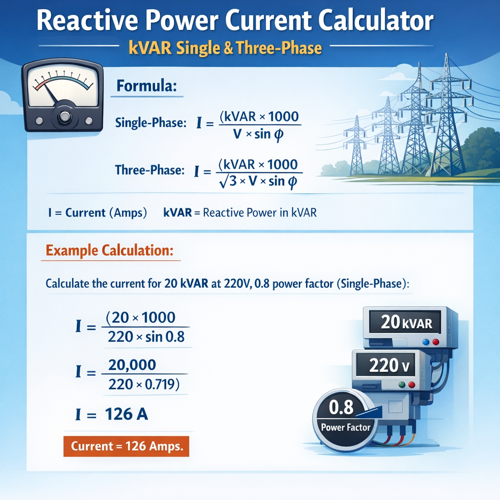
Reactive Power kVAr to Line Current Calculator (Single-Phase / Three-Phase)
- Convert reactive power from kVAr to VAr: Q (VAr) = Q (kVAr) × 1000
- Single-phase reactive current: I = Q / V
- Three-phase reactive current (balanced, line current): I = Q / (√3 × VL-L)
Where:
- I is the RMS line current in amperes (A).
- Q is the reactive power in volt-ampere reactive (VAr).
- V is the RMS voltage in volts (V). For three-phase, V is the line-to-line voltage VL-L.
- √3 ≈ 1.732 is the square root of 3, used for balanced three-phase systems.
If an optional design factor k is specified, the design current is: Idesign = k × I.
| Q (kVAr) | Voltage (V) | System | Approx. current I (A) |
|---|---|---|---|
| 5 | 230 | Single-phase | ≈ 21.7 A |
| 10 | 400 | Three-phase | ≈ 14.4 A |
| 25 | 400 | Three-phase | ≈ 35.9 A |
| 50 | 480 | Three-phase | ≈ 60.1 A |
Which voltage should I enter for a three-phase capacitor bank?
Enter the nominal line-to-line voltage of the system (for example, 400 V, 415 V, 460 V or 480 V). The calculator uses this line-to-line value together with √3 to compute the balanced line current.
Does the power factor change the result of this kVAr-based current calculation?
No. Once reactive power Q in kVAr is specified, the reactive current magnitude depends only on Q and the voltage according to the given formulas. Power factor is already implicit in how Q relates to the active power, but it does not directly enter the Q-to-I conversion.
How can I use the optional design factor field?
You can enter a multiplier above 1.00 to obtain a design current higher than the theoretical current, for example to account for capacitor tolerance, harmonic distortion, or future capacity (e.g., 1.10 for +10% margin). Leave it empty or at 1.00 if you do not want any margin.
Is the calculated current per phase or per line?
For single-phase, the result is the line current of that phase. For balanced three-phase systems, the result is the line current in each phase (the same in all three). The formula uses total three-phase reactive power and line-to-line voltage.
Scope and practical purpose of reactive-power current calculations
This document provides a rigorous, engineering-grade methodology to compute line or phase current produced by a given reactive power expressed in kVAr (kilovolt-ampere reactive). It covers single-phase and three-phase systems, pure reactive components, relationships with power factor, and examples for sizing conductors, protective devices, and power-factor correction equipment.
Fundamental theory: relationship between reactive power, apparent power and current
Reactive power Q (in VAR or kVAr) is the imaginary component of complex apparent power S. In circuit phasor form, S = P + jQ where P is active power and Q is reactive power. The magnitude of apparent power is |S| = V × I for single-phase, and |S| = √3 × V_LL × I_L for three-phase, where V_LL is line-to-line voltage and I_L is line current.
Key formulas (general)
Single-phase apparent power magnitude:
Three-phase apparent power magnitude:
Reactive power (definition in terms of apparent power and power angle):
Therefore, the magnitude of current associated with a given reactive power can be obtained by solving for I from Q = S × sin φ and substituting S expressions:
Single-phase reactive-current magnitude (I):
Three-phase reactive-current magnitude (line current I_L):
Alternatively, if power factor (PF = cos φ) is known, sin φ = √(1 − PF2), so the formulas can be written as:
Single-phase:
I = (kVAr × 1000) / (V × √(1 − PF2))
Three-phase:
I = (kVAr × 1000) / (√3 × V × √(1 − PF2))
Explanation of variables and typical engineering values
- Q: Reactive power in VAR. For engineering convenience often expressed in kVAr (1 kVAr = 1000 VAR).
- kVAr: Kilovolt-ampere reactive, common values in industrial systems: 1 kVAr to several thousand kVAr.
- V: For single-phase, the phase-to-neutral or line voltage (in volts). Typical residential/industrial nominal voltages: 120 V, 230 V, 277 V, 480 V.
- V (three-phase): Line-to-line nominal voltages: 208 V, 380 V, 400 V, 415 V, 480 V.
- I or I_L: Current in amperes (A).
- PF: Power factor (cos φ), dimensionless, range 0 to 1. Typical industrial lagging PF before correction: 0.7–0.95. After correction often 0.92–0.99.
- φ: Phase angle between voltage and current; sin φ = √(1 − PF2).
When to use each formula: practical guidance
- Use the single-phase form when the load is a single-phase installation or you are calculating per-phase current in a split single-phase distribution.
- Use the three-phase form when dealing with three-phase balanced loads and line currents in industrial distribution.
- If the reactive power is specified as the component being added or removed by capacitors (for PF correction), the current computed represents the reactive component of the line current.
- When designing conductors and protections, compute the total expected RMS current (vector sum of active and reactive components) using: I_total = S/(V × √3) or compute magnitudes of P and Q contributions and then combine: I_total = √(I_P2 + I_Q2).
Extensive tables with common values
The following tables show calculated reactive currents for common kVAr values and common voltages. These assume a purely reactive load (PF = 0 → sin φ = 1), giving direct current associated with reactive power. For corrected PF values use the formulas above with sin φ = √(1 − PF2).
| kVAr | Single-phase 120 V (A) | Single-phase 230 V (A) | Three-phase 208 V (A) | Three-phase 400 V (A) | Three-phase 480 V (A) |
|---|---|---|---|---|---|
| 1 | 8.33 | 4.35 | 2.78 | 1.44 | 1.20 |
| 5 | 41.67 | 21.74 | 13.89 | 7.22 | 6.00 |
| 10 | 83.33 | 43.48 | 27.78 | 14.44 | 12.00 |
| 50 | 416.67 | 217.39 | 138.89 | 72.22 | 60.00 |
| 100 | 833.33 | 434.78 | 277.78 | 144.44 | 120.00 |
| 500 | 4166.67 | 2173.91 | 1388.89 | 722.22 | 600.00 |
Notes: Values computed as I = (kVAr × 1000) / V for single-phase and I = (kVAr × 1000) / (√3 × V) for three-phase, with √3 ≈ 1.73205. Values rounded to two decimals where shown.
Adjusting tables for non-zero power factor
If the load has power factor PF (cos φ), reactive current is larger than the pure-reactive case by a factor 1 / sin φ. For example, with PF = 0.8, sin φ = √(1 − 0.82) = 0.6, so multiply the pure-reactive current by 1 / 0.6 ≈ 1.6667.
| kVAr | Three-phase 400 V, PF = 0.8 (A) | Three-phase 400 V, PF = 0.9 (A) | Multiplier vs PF=0 |
|---|---|---|---|
| 10 | 24.07 | 15.73 | PF=0.8 → ×1.6667; PF=0.9 → ×1.1111 |
| 50 | 120.37 | 78.66 | See multipliers |
| 100 | 240.74 | 157.31 | — |
Practical engineering considerations and combinations with active power
Often you need total current rather than only the reactive component. When both P and Q are present, compute phase or line RMS current from apparent power S magnitude. For three-phase balanced systems:
S = √(P2 + Q2)
Alternatively compute per-component currents then combine by root-sum-square:
I_P = P / (√3 × V), I_Q = Q / (√3 × V), I_total = √(I_P2 + I_Q2).
Example: combining P and Q
Given: three-phase load, V = 400 V, P = 150 kW, Q = 100 kVAr.
- Compute S = √(1502 + 1002) kVA = √(22500 + 10000) = √32500 ≈ 180.28 kVA.
- Line current I = (180.28 kVA × 1000) / (√3 × 400 V) = 180280 / 692.82 ≈ 260.2 A.
- Reactive current I_Q = (100 kVAr × 1000) / (√3 × 400) ≈ 144.4 A; active current I_P ≈ 216.6 A. Check: √(216.62 + 144.42) ≈ 260.2 A consistent.
Detailed worked examples (at least two)
Example 1 — Single-phase system: compute current for reactive component
Problem statement: A single-phase industrial furnace produces a reactive demand of 25 kVAr at a voltage of 230 V. Determine the reactive current magnitude for two cases: a) purely reactive load (PF = 0), b) load with overall power factor PF = 0.85 (lagging).
Given:
- Q = 25 kVAr = 25,000 VAR
- V = 230 V
Case b) PF = 0.85 → sin φ = √(1 − 0.852) = √(1 − 0.7225) = √0.2775 ≈ 0.52686
Interpretation: With the same reactive power, the reactive current magnitude increases when PF is closer to unity (because sin φ decreases). This is important when evaluating harmonic filters, capacitor bank switching devices and conductor heating under mixed loads.
Example 2 — Three-phase power-factor correction scenario
Problem statement: An industrial plant operates a balanced three-phase load at 415 V line-to-line and has an active demand of P = 350 kW at a measured power factor of 0.78 lagging. The engineer wants to improve PF to 0.95 lagging using capacitor banks. Calculate the required kVAr to shift PF from 0.78 to 0.95 and determine the reactive current associated with the corrective capacitor bank at 415 V.
Step 1: Compute initial reactive power Q1 using Q1 = P × tan φ1 where tan φ1 = √(1 / PF2 − 1).
Compute φ1: PF1 = 0.78 → tan φ1 = √(1 / 0.782 − 1) = √(1 / 0.6084 − 1) = √(1.643 − 1) = √0.643 ≈ 0.802.
Q1 = P × tan φ1 = 350 kW × 0.802 ≈ 280.7 kVAr (lagging).
Step 2: Compute target reactive power Q2 for PF2 = 0.95.
tan φ2 = √(1 / 0.952 − 1) = √(1 / 0.9025 − 1) = √(1.108 − 1) = √0.108 ≈ 0.328.
Q2 = 350 kW × 0.328 ≈ 114.8 kVAr.
Step 3: Capacitor requirement (kVAr to be installed) = Qc = Q1 − Q2 = 280.7 − 114.8 ≈ 165.9 kVAr.
For a capacitor bank providing Qc its phase angle is −90°, but when calculating current magnitude for the reactive contribution we can use sin φ = 1 (pure reactive). So:
I_c = (165.9 × 1000) / (√3 × 415) = 165900 / (1.73205 × 415) ≈ 165900 / 718.0 ≈ 231.1 A
Step 5: Effect on line current: compute initial and final line currents using S = √(P2 + Q2).
Initial S1 = √(3502 + 280.72) ≈ √(122500 + 78796) ≈ √201296 ≈ 448.66 kVA.
I1 = (448.66 × 1000) / (√3 × 415) ≈ 448660 / 718.0 ≈ 624.9 A.
Final S2 = √(3502 + 114.82) ≈ √(122500 + 13177) ≈ √135677 ≈ 368.46 kVA.
I2 = 368460 / 718.0 ≈ 513.4 A.
Thus the capacitor bank supplying 165.9 kVAr reduces line current by ≈111.5 A, which is consistent with the reactive current magnitude computed and resulting vector reduction.
Design tips, limitations and safety considerations
- Always use RMS values for currents and voltages in these formulas.
- Verify voltage basis: use phase-to-neutral voltage for single-phase or phase currents when appropriate; use line-to-line voltage for balanced three-phase, line currents.
- Consider unbalance: the three-phase formula assumes balanced conditions. For unbalanced loads, compute per-phase separately.
- When sizing conductors and protective devices, account for harmonics and inrush currents associated with capacitor switching and motor starts. Use derating factors where required by local standards.
- Follow applicable standards for PF correction equipment installation, e.g., overcurrent protection for capacitor banks, discharge resistors, and safety interlocks.
Reference standards and authoritative guidance
Relevant international standards and authoritative resources include:
- IEC 60038 — IEC Standard Voltages: provides nominal voltages used in tables. (https://webstore.iec.ch/publication/6166)
- IEEE Std 141 — IEEE Recommended Practice for Electric Power Distribution for Industrial Plants ("IEEE Green Book") — guidance on power factor correction and distribution design. (https://standards.ieee.org/standard/141-1993.html)
- IEEE Std 399 — IEEE Recommended Practice for Industrial and Commercial Power Systems Analysis ("IEEE Brown Book"). (https://standards.ieee.org/standard/399-1997.html)
- IEC 61000 series — Electromagnetic compatibility (EMC), harmonics and associated effects when installing capacitor banks and filters. (https://www.iec.ch)
- NEMA and local electrical codes — for equipment ratings, short-circuit calculations and conductor ampacity tables.
Verification, rounding and unit handling
- Always track units: convert kVAr to VAR by multiplying by 1000.
- Round only at the final step to avoid propagation error; keep at least 4–6 significant digits during intermediate calculations.
- For high-power systems (hundreds of kVAr), consider system impedance, voltage drop and the effect of capacitive reactance on resonance with line inductance; consult harmonic analysis guides.
Frequently used quick-reference formulas
Single-phase reactive current magnitude (explicit):
I (A) = (kVAr × 1000) / (V × √(1 − PF2))
Three-phase reactive current magnitude (explicit):
I (A) = (kVAr × 1000) / (√3 × V × √(1 − PF2))
Change in kVAr required to correct PF from PF1 to PF2 for given active power P:
where tan φ = √(1 / PF2 − 1).
Summary of recommended workflow for an engineer
- Obtain accurate P, Q measurements and voltage levels. Verify whether values are per-phase or total three-phase.
- Decide whether you compute reactive current for pure reactive components or for combined P and Q. Use the appropriate formula.
- Perform conversion of units; keep consistent units (V, A, kW, kVAr).
- Compute currents, then check against conductor ampacity, protective settings, and capacitor bank ratings.
- Consider harmonics and switching transients; include mitigation devices (detuning reactors, filters) where necessary.
Further reading and online tools
- IEEE and IEC published standards as listed above for normative requirements.
- Manufacturers of capacitor banks and power-quality equipment provide application notes and calculators for PF correction and harmonic sizing (e.g., reputable manufacturers' engineering guides).
- Open-source power system calculators and commercial software (ETAP, DIgSILENT PowerFactory, SKM PowerTools) provide detailed models including unbalance and harmonics.
Final engineering notes
Perform site measurements where possible before making permanent installations. Use the formulas and tables above to size equipment conservatively, and consult local wiring regulations and safety standards. For complex systems, perform a detailed power-system transient and harmonic study to avoid resonance and ensure compliance with grid interconnection rules.
Selected normative references (direct links)
- IEC 60038 — Standard voltages: https://webstore.iec.ch/publication/6166
- IEEE Std 141 — https://standards.ieee.org/standard/141-1993.html
- IEEE Std 399 — https://standards.ieee.org/standard/399-1997.html
- IEC (general site for EMC and harmonics guidance) — https://www.iec.ch