This article provides technical methods for calculating motor starting voltage drop impacts on busbars worldwide.
Detailed formulas, standards, and examples allow engineers to predict bus and motor behavior during startup.
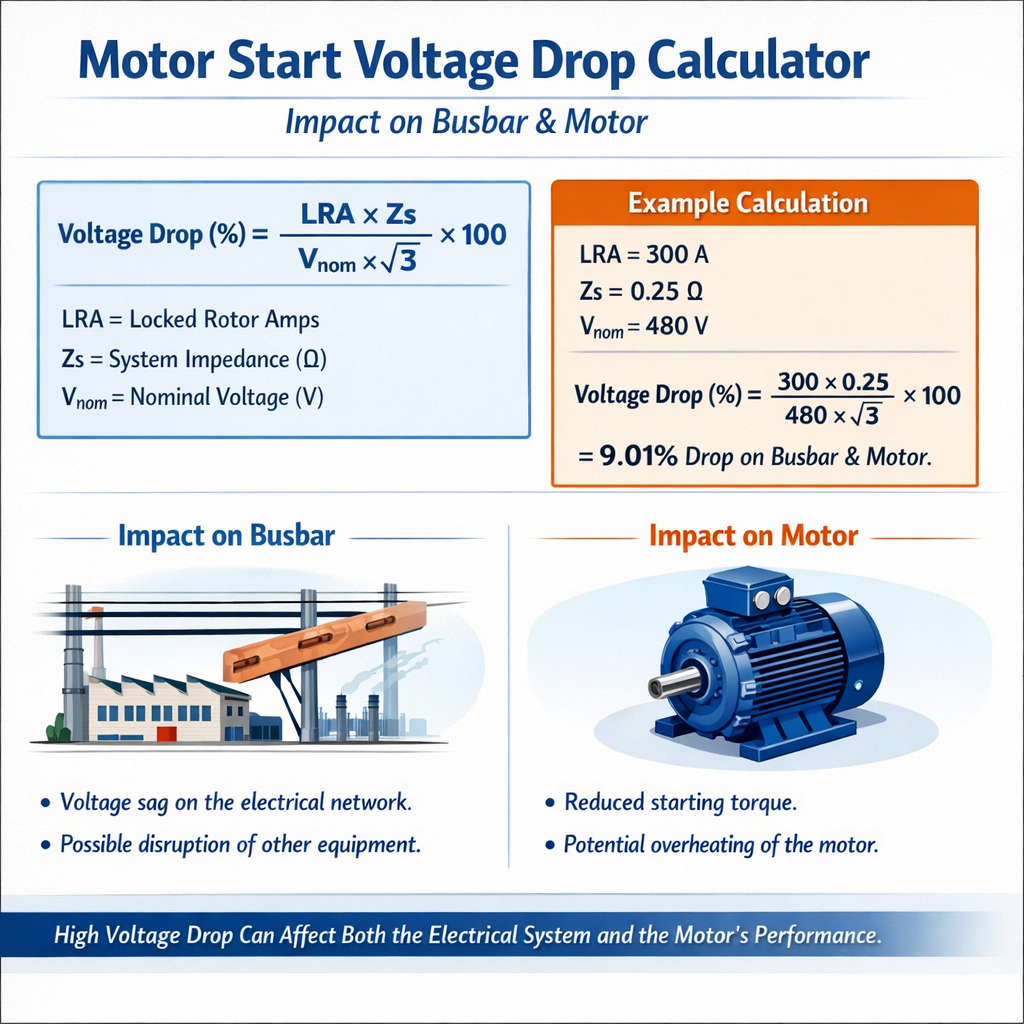
Voltage Drop During Motor Starting – Impact on Bus and Motor Terminals
Understanding voltage drop during motor startup and its system impact
Motor starting is a transient event that draws high inrush or locked-rotor current, producing a voltage drop across the upstream network impedance. This drop affects bus voltage, other connected loads, and can cause nuisance tripping or failed starts.
Quantifying that drop requires knowledge of motor starting current, supply and feeder impedances, system X/R ratios, and the applied protection and voltage tolerance limits. The following sections provide formulas, parameter definitions, typical values, and worked examples.
Fundamental electrical relationships and notation
Use these primary expressions for three-phase systems unless otherwise specified.
Basic magnitude form for three-phase voltage drop
Where:
- I = line (phase) current during the event (A)
- Z = per-phase magnitude of feeder impedance (Ω)
- √3 = root 3 factor for three-phase line-to-line quantities (≈1.732)
To express the RMS voltage drop expressed as a percentage of nominal line-to-line voltage V_LL:
Alternatively, if the power factor or angle φ of the current with respect to voltage is known, separate resistive and reactive components:
Variable explanations and typical values:
- R = per-phase resistance of feeder + bus (Ω). Typical for copper conductors: 0.0005 … 0.05 Ω/m depending on conductor size.
- X = per-phase reactance of feeder + bus (Ω). Typical line reactance depends on conductor geometry, e.g., 0.00008 … 0.0008 Ω/m.
- Z = √(R^2 + X^2) (Ω)
- I = during starting event, use locked-rotor current I_LR or locked-rotor multiple × rated current I_rated.
- V_LL = nominal line-to-line voltage (V), e.g., 400 V, 480 V, 690 V.
- φ = angle between current and voltage; for induction motor starting φ≈90° (highly inductive) so cosφ ~ 0…0.3 for transient conditions; conservative approach uses reactive contribution dominantly.
Key motor and system parameters
Several tabulated parameters are used repeatedly in calculations: motor starting multipliers, typical cable impedances per size, and representative X/R ratios. The tables below collect common values for engineering calculations.
| Motor Type / Standard | Locked-Rotor Multiple of Rated Current (I_LR / I_rated) | Notes |
|---|---|---|
| NEMA Design A | ~6 – 8 | General purpose; moderate starting torque |
| NEMA Design B | ~6 – 8 | Most common; typical industrial motors |
| NEMA Design C | ~5 – 7 | High starting torque |
| NEMA Design D | ~4 – 6 | High inertia or load torque |
| IEC (standard induction motors) | ~5 – 8 | Varies by construction and rated slip |
| Conductor Size (mm²) | R @20°C (Ω/km) | X (Ω/km) | Notes |
|---|---|---|---|
| 16 mm² | 1.15 | 0.080 | Small power feeder |
| 35 mm² | 0.524 | 0.075 | Common motor feeder up to ~30 kW |
| 50 mm² | 0.387 | 0.073 | Used for higher currents |
| 95 mm² | 0.206 | 0.068 | Large feeders |
| 185 mm² | 0.108 | 0.063 | Very large feeders |
| Component | Typical X/R | Effect on voltage drop |
|---|---|---|
| Short cable feeder | 0.1 – 0.3 | Low reactance, resistive drop significant |
| Long overhead line | 1 – 10 | Reactive drop dominates, transient oscillatory effects |
| Transformer short-circuit | 0.1 – 0.5 | Can limit motor starting voltage due to internal impedance |
Detailed formula set for practical calculations
To compute the voltage at the motor terminals during the start event, follow these steps and formulas.
Step 1 — Determine starting current
Where:
- I_rated = motor rated current (A) from nameplate or catalogue
- k_LR = locked-rotor multiplier (typical values in the table above)
Step 2 — Compute feeder per-phase impedance for the run length
Where L = one-way feeder length in meters. For three-phase systems, consider return paths and parallel conductors if present. Add transformer or busbar resistances equivalent per phase when relevant.
Step 3 — Per-phase impedance magnitude
Step 4 — Voltage drop magnitude and resulting motor terminal voltage
Express as percentage:
These formulas assume balanced three-phase symmetrical conditions and linear system impedances. Transient sub-synchronous dynamics, saturation, and non-linear behaviors of protection devices require time-domain simulation for high fidelity.
Protection and operational criteria to check after calculation
- Verify minimum acceptable starting voltage per motor manufacturer (often ≥ 80% of nominal for successful acceleration).
- Assess undervoltage relay pickup and reset settings to avoid nuisance trips.
- Check thermal effects of prolonged reduced-voltage start or stalled motor on protection curves.
- For multiple motors starting concurrently, perform combined current vector summation and worst-case drop calculations.
Worked example 1 — 15 kW motor fed through 35 mm² copper cable
Problem statement: A 15 kW, 400 V, three-phase induction motor with rated current I_rated = 28 A. The motor is a NEMA Design B with expected locked-rotor multiplier k_LR = 6. The feeder is 30 m of 35 mm² copper cable. Nominal supply: 400 V LL. Calculate the expected motor terminal voltage during locked-rotor starting. Use R_per_km = 0.524 Ω/km and X_per_km = 0.075 Ω/km for 35 mm².
- Compute starting current:
I_start = k_LR × I_rated = 6 × 28 A = 168 A
- Compute feeder impedance for L = 30 m:
R_feeder = (0.524 × 30) / 1000 = 0.01572 ΩX_feeder = (0.075 × 30) / 1000 = 0.00225 Ω
Assume negligible busbar resistance; assume transformer contribution small for this feeder, or include if known.
- Compute per-phase magnitude:
Z = √(R_total^2 + X_total^2) = √(0.01572^2 + 0.00225^2)
Z ≈ √(0.000247 + 0.00000506) ≈ √(0.000252) ≈ 0.01587 Ω
- Compute voltage drop:
V_drop = √3 × I_start × Z = 1.732 × 168 A × 0.01587 Ω
V_drop ≈ 1.732 × 168 × 0.01587 ≈ 4.62 V
- Compute motor terminal voltage:
V_motor = V_nominal − V_drop = 400 − 4.62 = 395.38 VV_motor% = (395.38 / 400) × 100 ≈ 98.8%
Interpretation: The small feeder length and low impedance yield a modest voltage drop. The motor sees ≈98.8% of nominal during locked-rotor current — acceptable for starting. Note: motor internal voltage drop due to internal reactance and supply transformer impedance were neglected; add those if they are significant.
Worked example 2 — 200 kW motor with long feeder and transformer contribution
Problem statement: A 200 kW, 690 V three-phase motor, I_rated = 210 A. Locked-rotor multiplier k_LR = 6.5 (manufacturer). Feeder length L = 200 m, conductor 95 mm² copper with R_per_km = 0.206 Ω/km and X_per_km = 0.068 Ω/km. Motor is fed from a transformer whose equivalent per-phase impedance referred to secondary is Z_tr = 0.02 Ω (magnitude). Determine motor terminal voltage during locked-rotor start and percent voltage.
- Starting current:
I_start = 6.5 × 210 A = 1365 A
- Feeder per-phase impedance:
R_feeder = (0.206 × 200) / 1000 = 0.0412 ΩX_feeder = (0.068 × 200) / 1000 = 0.0136 Ω
- Total per-phase R and X including transformer:
R_total = R_feeder + R_tr (use R_tr from Z_tr and X_tr if known). If Z_tr = 0.02 Ω and assume transformer X dominates with X_tr ≈ 0.018 Ω and R_tr ≈ 0.007 Ω (an example), then:
R_total = 0.0412 + 0.007 = 0.0482 ΩX_total = 0.0136 + 0.018 = 0.0316 Ω - Per-phase impedance magnitude:
Z = √(0.0482^2 + 0.0316^2) ≈ √(0.002323 + 0.000999) ≈ √(0.003322) ≈ 0.05765 Ω
- Voltage drop:
V_drop = √3 × I_start × Z = 1.732 × 1365 × 0.05765 ≈ 136.1 V
- Motor terminal voltage:
V_motor = 690 − 136.1 = 553.9 VV_motor% = (553.9 / 690) × 100 ≈ 80.3%
Interpretation: The motor sees ≈80.3% of nominal during locked-rotor conditions. Many motors will still accelerate at this voltage, but margin is limited. Check the manufacturer minimum starting voltage — some motors may require at least 80–85% to successfully start under load. Also check protection settings; undervoltage relays may trip if set near this value. Consider starting methods such as reduced-voltage starters or soft starters to manage inrush and reduce feeder stress.
Multiple motors starting and simultaneous start scenarios
When multiple motors start simultaneously or in sequence, vector summation of currents and phasors is required. Conservative scalar summation (sum of magnitudes) overestimates drop; phasor summation with known angles is more accurate. For safe design, evaluate worst-case combinations:
- Calculate individual I_start phasors considering motor starting power factor (often low). Example: use angle φ_start ≈ 80–85° (cosφ ≈ 0.17–0.10) for locked rotor.
- Sum phasors: I_total = √( (Σ I_i cosφ_i)^2 + (Σ I_i sinφ_i)^2 ).
- Use I_total in V_drop = √3 × I_total × Z to compute drop.
Alternatively, perform time-domain or EMTP simulations for highly coupled systems or where protection interactions are critical.
Mitigation strategies to control voltage drop impact
- Reduce feeder impedance: increase conductor cross-section, shorten run length, or provide parallel conductors.
- Improve source stiffness: lower transformer impedance by using a larger or parallel transformer, or reconfigure supply.
- Use reduced-voltage starting methods: star-delta, autotransformer, soft-starter, or VFD to limit starting current and voltage sag.
- Stagger start times of large motors to avoid coincident inrush.
- Install dynamic voltage support: synchronous condensers, STATCOMs, or capacitor banks to help maintain voltage during transient events (note capacitors can interact negatively with motor starting harmonics; analyze carefully).
Standards, normative references and authoritative resources
Use the following standards and guidance documents for regulatory and design requirements:
- IEC 60034 — Rotating electrical machines: specifications regarding performance and testing of induction motors. (https://www.iec.ch)
- IEC 60909 — Short-circuit currents in three-phase AC systems; useful for transformer and system impedance modeling. (https://www.iec.ch)
- NEMA MG1 — Motors and generators: provides guidance on locked-rotor currents and design categories. (https://www.nema.org)
- IEEE Std 141 (Green Book) — Electric Power Distribution for Industrial Plants; includes practical guidance on voltage drop and motor starting. (https://standards.ieee.org)
- IEEE Std 142 (Green Book) and IEEE Std 242 — grounding and system modeling for power systems.
- NFPA 70 (NEC) — National Electrical Code: voltage drop recommendations for branch circuits and feeders in installations (consult local code amendments). (https://www.nfpa.org)
Engineering standards sites and publishers often require purchase or subscription for full text; use summaries and annex guidance as permitted. For authoritative application notes, consult motor manufacturers (e.g., ABB, Siemens, WEG) and transformer suppliers for manufacturer-specific impedance data and starting recommendations.
Practical notes and modeling cautions
- Locked-rotor current from nameplates is a typical steady locked-rotor value; the actual dynamic inrush at the instant of energization can be higher due to transient effects—model with worst-case multipliers when necessary.
- Transformer inrush and saturation during energization may temporarily increase drop; represent transformer magnetizing inrush separately in time-domain studies.
- Cable impedance values are temperature dependent; resistance increases with conductor temperature. Use appropriate correction for long-duration starts or repeated starts causing heating.
- Protective devices respond to time-current characteristics; verify that reduced terminal voltage does not cause prolonged thermal stress or current that exceeds protection time limits.
- Perform harmonic assessment if soft starters or VFDs are present; harmonic currents can increase losses and effective impedance.
Checklist for engineers when assessing motor starting voltage drop
- Collect accurate motor data: rated current, locked-rotor current or multiplier, recommended minimum starting voltage, starting power factor estimate.
- Measure or obtain feeder impedance: conductor R and X per length, length, and number of conductors in parallel.
- Include transformer and upstream network impedances converted to the same base (per-phase values).
- Decide worst-case start scenario: single motor start, multiple simultaneous starts, or upstream contingencies.
- Compute V_drop, V_motor_terminal, and compare to manufacturer limits and protection settings.
- Select mitigation if V_motor_terminal below acceptable threshold.
Further reading and authoritative links
- IEC Publications: https://www.iec.ch — search for IEC 60034 and IEC 60909 for rotating machines and short-circuit calculations.
- NEMA MG1 Motor Standards: https://www.nema.org — motor design categories and performance characteristics.
- IEEE Standards and Tutorials: https://standards.ieee.org and IEEE Xplore for IEEE Std 141 and application guides.
- NFPA (NEC) guidance on voltage drop and installation rules: https://www.nfpa.org
- Manufacturer technical papers: ABB, Siemens, WEG, Schneider Electric application notes on motor starting and voltage drop (search vendor sites for application notes and calculators).
Summary of engineering approach
Follow a methodical workflow: obtain accurate motor and network parameters, compute per-phase impedance for the event, estimate starting currents realistically, apply the three-phase voltage drop formula, and evaluate motor terminal voltage versus limits. Use phasor summation for multiple units and simulate time-domain behavior for complex or marginal systems. Where terminal voltage falls below acceptable levels, apply mitigation strategies including feeder upgrades, reduced-voltage starting, or supply reinforcement.
Accurate modeling, normative reference checks, and validation with manufacturer data reduce operational risk and ensure reliable motor starts without undue stress on the distribution network.