XL = 2πfL | L = XL ÷ (2πf) | f = XL ÷ (2πL)📊 Quick Reference Table
| f (Hz) | L (mH) | XL (Ω) |
|---|---|---|
| 50 | 10 | 3.14 |
| 50 | 100 | 31.42 |
| 60 | 50 | 18.85 |
| 60 | 100 | 37.70 |
| 60 | 500 | 188.50 |
| 400 | 10 | 25.13 |
| 1,000 | 5 | 31.42 |
❓ Quick FAQ
What is the XL formula?
XL = 2πfL, where f is frequency in Hz and L is inductance in henries.
What unit is XL measured in?
Ohms (Ω), same as resistance.
The inductive reactance calculator on this page computes XL using the fundamental AC formula XL = 2πfL. Inductive reactance is the opposition that an inductor presents to alternating current — it increases with both frequency and inductance, and it is measured in ohms (Ω), the same unit as resistance. Unlike resistance, however, inductive reactance causes the current to lag the voltage by 90°, which is why it plays a central role in power-factor correction, filter design, motor starting, and transformer impedance calculations.
Whether you are designing an LC filter for a VFD output, checking the starting reactance of a motor winding, sizing a current-limiting reactor for a capacitor bank, or solving a physics problem about dimensional analysis, this guide gives you the complete XL formula in AC, step-by-step worked examples, the dimensional formula of inductive reactance, and a practical comparison of XL versus XC. All formulas follow the definitions established by NIST SI standards and IEC 60050.
Inductive Reactance Reference Table
The table below lists common frequency and inductance combinations encountered in power systems (50/60 Hz), aviation electronics (400 Hz), and audio/RF applications (1 kHz and above). All values are calculated using XL = 2πfL.
| Frequency (Hz) | Inductance | XL (Ω) | Typical Application |
|---|---|---|---|
| 50 | 1 mH (0.001 H) | 0.314 | Small choke in 50 Hz power supply |
| 50 | 10 mH (0.01 H) | 3.14 | Line reactor for VFD input |
| 50 | 100 mH (0.1 H) | 31.42 | Current-limiting reactor |
| 60 | 1 mH (0.001 H) | 0.377 | Small choke in 60 Hz system |
| 60 | 10 mH (0.01 H) | 3.77 | Line reactor for VFD input |
| 60 | 50 mH (0.05 H) | 18.85 | Motor starting reactor |
| 60 | 100 mH (0.1 H) | 37.70 | Large current-limiting reactor |
| 60 | 500 mH (0.5 H) | 188.50 | Power transformer leakage reactance |
| 60 | 1 H | 376.99 | Large inductor or iron-core choke |
| 400 | 1 mH (0.001 H) | 2.51 | Aircraft 400 Hz power system filter |
| 400 | 10 mH (0.01 H) | 25.13 | 400 Hz motor winding |
| 1,000 | 5 mH (0.005 H) | 31.42 | Audio crossover network |
| 1,000 | 100 mH (0.1 H) | 628.32 | Audio filter inductor |
| 10,000 | 1 mH (0.001 H) | 62.83 | RF choke / EMI filter |
| 1,000,000 | 10 µH (0.00001 H) | 62.83 | RF circuit inductor |
Notice the pattern: the same inductance produces a much higher reactance at higher frequencies. A 10 mH inductor presents only 3.77 Ω at 60 Hz but 62.83 Ω at 1 kHz — that is why inductors are effective at blocking high-frequency noise while allowing low-frequency power to pass through.
XL Formula: How to Calculate Inductive Reactance Step by Step
The XL formula in AC circuits is derived from Faraday’s law of electromagnetic induction and the sinusoidal nature of alternating current. It states that the opposition an inductor presents to AC is directly proportional to both the frequency and the inductance.
Where:
- XL = inductive reactance in ohms (Ω)
- f = frequency in hertz (Hz)
- L = inductance in henries (H)
- 2π ≈ 6.2832 (converts frequency in Hz to angular frequency ω in rad/s)
An equivalent form uses angular frequency directly:
Dimensional formula of inductive reactance
Since XL is measured in ohms, its dimensional formula is the same as for resistance. In SI base units, one ohm equals one volt per ampere, which expands to:
This means: mass (kg) × length² (m²) ÷ time³ (s³) ÷ current² (A²). You can verify this by expanding the units of 2πfL: frequency (Hz = s⁻¹) × inductance (H = kg⋅m²⋅s⁻²⋅A⁻²) gives kg⋅m²⋅s⁻³⋅A⁻² = Ω. The dimensional formula is a common exam topic in physics — it confirms that inductive reactance has the same physical dimensions as resistance, even though its origin is electromagnetic induction rather than ohmic dissipation.
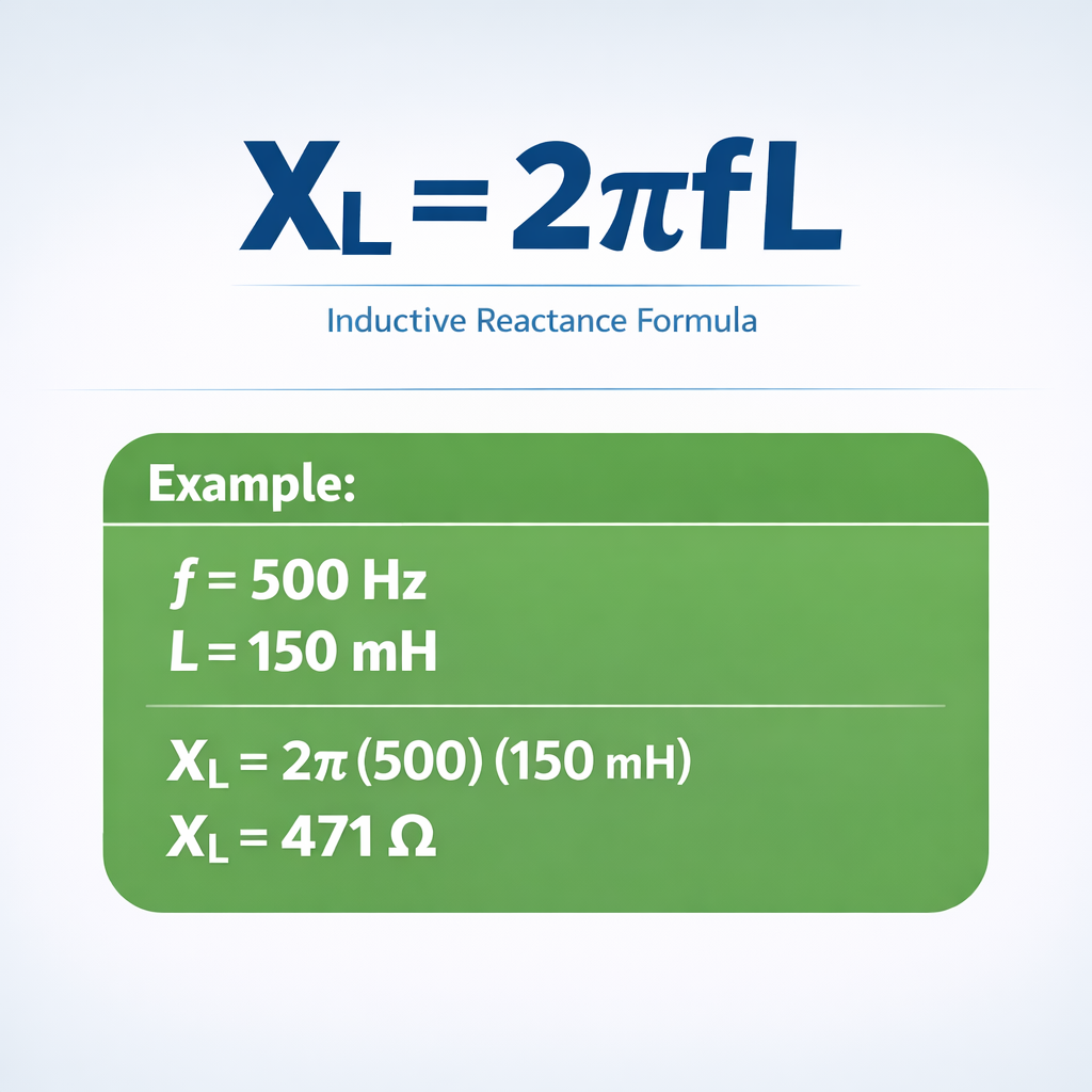
Step-by-step: Calculate XL for a 50 mH inductor at 60 Hz
- Identify values: f = 60 Hz, L = 50 mH = 0.05 H.
- Apply formula: XL = 2π × 60 × 0.05.
- Calculate: XL = 6.2832 × 60 × 0.05 = 6.2832 × 3 = 18.85 Ω.
- Context: 18.85 Ω of inductive reactance at 60 Hz — this is the impedance a motor-starting reactor or line reactor would present to limit inrush current.
Rearranged formulas
Use this form when you know the desired reactance and frequency and need to find the required inductance — for example, when specifying a line reactor to achieve a target percent impedance at the system frequency.
Use this form when you know the reactance and inductance and need to find the frequency — useful in resonance analysis and filter design.
XL vs. XC — Inductive vs. Capacitive Reactance
AC circuits contain two types of reactance: inductive (XL) and capacitive (XC). They oppose each other — when they are equal, the circuit is at resonance. The table below summarizes their key differences.
| Attribute | XL (Inductive) | XC (Capacitive) |
|---|---|---|
| Formula | 2πfL | 1 ÷ (2πfC) |
| Unit | Ohms (Ω) | Ohms (Ω) |
| Effect on current | Current lags voltage by 90° | Current leads voltage by 90° |
| Frequency relationship | Increases with frequency | Decreases with frequency |
| At DC (0 Hz) | 0 Ω (short circuit) | ∞ Ω (open circuit) |
| At ∞ Hz | ∞ Ω (open circuit) | 0 Ω (short circuit) |
| Dimensional formula | [M L² T⁻³ A⁻²] | [M L² T⁻³ A⁻²] |
| Common components | Coils, transformers, motors, solenoids | Capacitors, capacitor banks |
| Energy storage | Magnetic field (½LI²) | Electric field (½CV²) |
| Resonance condition | XL = XC → 2πfL = 1/(2πfC) → fres = 1/(2π√(LC)) | |
The net reactance of a series RLC circuit is X = XL − XC. When XL > XC, the circuit is inductive (current lags). When XC > XL, the circuit is capacitive (current leads). At resonance (XL = XC), the net reactance is zero and the impedance equals the pure resistance R — this is the principle behind tuned circuits, power-factor correction, and filter design.
Solving for L or f from XL (Inverse Calculations)
| Known Values | Solve For | Formula | Example |
|---|---|---|---|
| XL = 37.70 Ω, f = 60 Hz | L | L = XL ÷ (2πf) | 37.70 ÷ (6.2832 × 60) = 0.1 H = 100 mH |
| XL = 31.42 Ω, L = 5 mH | f | f = XL ÷ (2πL) | 31.42 ÷ (6.2832 × 0.005) = 1,000 Hz |
| XL = 18.85 Ω, f = 60 Hz | L | L = XL ÷ (2πf) | 18.85 ÷ 376.99 = 0.05 H = 50 mH |
| XL = 62.83 Ω, L = 10 µH | f | f = XL ÷ (2πL) | 62.83 ÷ (6.2832 × 0.00001) = 1,000,000 Hz = 1 MHz |
These inverse calculations are essential when designing filters, specifying reactors, or analyzing unknown inductors with an impedance analyzer. Use our Ohm’s Law Calculator for related resistance and current calculations.
6 Solved Examples — Real-World Inductive Reactance Problems
Example 1 — Motor Starting Reactor at 60 Hz
Data: f = 60 Hz, L = 50 mH = 0.05 H.
Formula: XL = 2πfL
Calculation: 2π × 60 × 0.05 = 6.2832 × 3 = 18.85 Ω
A 50 mH reactor in series with a motor winding limits starting current by adding 18.85 Ω of impedance. On a 480 V system, this reactor limits the initial inrush to about 480 ÷ 18.85 ≈ 25.5 A per phase — significantly less than the full locked-rotor current.
Example 2 — VFD Line Reactor at 60 Hz
Data: f = 60 Hz, L = 1.5 mH = 0.0015 H.
Formula: XL = 2πfL
Calculation: 2π × 60 × 0.0015 = 6.2832 × 0.09 = 0.565 Ω
A 1.5 mH line reactor adds only 0.565 Ω of impedance at 60 Hz — but it provides 3–5% impedance on a typical 480 V, 30 A drive, which is enough to reduce harmonic distortion and protect the VFD from voltage spikes on the bus.
Example 3 — Transformer Leakage Reactance
Data: f = 50 Hz, L = 200 mH = 0.2 H.
Formula: XL = 2πfL
Calculation: 2π × 50 × 0.2 = 6.2832 × 10 = 62.83 Ω
62.83 Ω of leakage reactance in a 50 Hz transformer. This value determines the short-circuit impedance (%Z) of the transformer, which in turn limits the fault current the downstream switchgear must handle. For more on fault currents, see our Available Fault Current Calculator.
Example 4 — Audio Crossover Inductor at 1 kHz
Data: f = 1,000 Hz, L = 5 mH = 0.005 H.
Formula: XL = 2πfL
Calculation: 2π × 1,000 × 0.005 = 6.2832 × 5 = 31.42 Ω
31.42 Ω at 1 kHz. In a speaker crossover network, this inductor blocks frequencies above the crossover point from reaching the woofer. At 10 kHz the same inductor presents 314.2 Ω — effectively an open circuit for the tweeter range.
Example 5 — Aircraft 400 Hz Power System
Data: f = 400 Hz, L = 10 mH = 0.01 H.
Formula: XL = 2πfL
Calculation: 2π × 400 × 0.01 = 6.2832 × 4 = 25.13 Ω
25.13 Ω. Aircraft power systems operate at 400 Hz (instead of 50/60 Hz) to reduce the size and weight of transformers and motors. The higher frequency means the same inductor presents 6.7× more reactance than at 60 Hz — so smaller inductors can achieve the same filtering effect.
Example 6 — Finding Inductance from Measured Reactance
Data: XL = 47.12 Ω (measured), f = 60 Hz.
Formula: L = XL ÷ (2πf)
Calculation: 47.12 ÷ (2π × 60) = 47.12 ÷ 376.99 = 0.125 H = 125 mH
By measuring the reactance at a known frequency and using the inverse formula, you can determine the inductance of an unknown coil without disassembling it — a common technique in field troubleshooting of transformers and reactors.
Practical Applications of Inductive Reactance
Inductive reactance shows up in virtually every AC system. Here are the contexts where you will use the XL = 2πfL calculation most often.
Power-factor correction
Motor and transformer loads are inductive — they draw lagging reactive current that increases the kVA demand without doing useful work. By installing capacitor banks that provide capacitive reactance (XC) equal to the excess inductive reactance (XL), you cancel the reactive component and bring the power factor closer to 1.0. Calculating XL of the load is the first step in sizing the correction capacitors. For related power calculations, see our Amps to kW calculator.
Harmonic filtering
VFDs and rectifiers inject harmonic currents (5th, 7th, 11th, 13th) into the power system. Harmonic filters use series-tuned LC circuits where XL = XC at the target harmonic frequency. Calculating the required inductance to achieve a specific reactance at each harmonic frequency is a direct application of the 2πfL formula.
Transformer impedance
The percent impedance (%Z) of a transformer is dominated by its leakage reactance. When you measure the short-circuit impedance and subtract the winding resistance, the remainder is XL. This value determines the maximum available fault current and is required for arc-flash studies and coordination studies. See our Arc Flash Energy Calculator for related protection analysis.
Motor starting and inrush current
When a motor starts, its rotor is stationary and the winding presents mostly inductive reactance (plus a small resistance). The locked-rotor current is approximately V ÷ XL. Adding an external reactor in series temporarily increases XL to limit the inrush — a technique called reactor starting or impedance starting.
Quick Equivalences
XL Formula in AC
XL = 2πfL
The fundamental inductive reactance formula for AC circuits. f in Hz, L in henries, result in ohms.
XL Formula AC (alternate)
XL = ωL
Same formula using angular frequency ω = 2πf in rad/s. Commonly used in phasor analysis and control theory.
Inductive Reactance Dimensional Formula
[M L² T⁻³ A⁻²]
Same as ohm: kg⋅m²⋅s⁻³⋅A⁻². Derived by multiplying [Hz = T⁻¹] × [H = M L² T⁻² A⁻²].
XL Inductance Formula
L = XL ÷ (2πf)
Rearranged to solve for inductance. Useful when you measure reactance with an impedance meter and need the inductance value.
XL Unit
Ohm (Ω)
Inductive reactance is measured in ohms — the same unit as resistance. Both oppose current flow, but reactance stores and releases energy instead of dissipating it.
XL = 2πfL
Direct computation
At 60 Hz, 100 mH: XL = 2π × 60 × 0.1 = 37.70 Ω. At 50 Hz, same inductor: 31.42 Ω.
Formula for XL and XC
XL = 2πfL | XC = 1/(2πfC)
XL increases with frequency; XC decreases. At resonance XL = XC, giving fres = 1/(2π√LC).
Dimensions of Inductive Reactance
[M¹ L² T⁻³ A⁻²]
Identical to resistance. Confirms XL has the same physical dimensions as R, despite different physical origins.
XL Calculator
Use the tool above
Enter frequency and inductance to compute XL, or switch to solve for L or f from a known reactance value.
Inductor Reactance Calculator
XL = 2πfL (same tool)
Whether you call it “inductor reactance” or “inductive reactance,” the formula and calculator are the same.
FAQ — Inductive Reactance XL
What is the formula for inductive reactance?
XL = 2πfL. Multiply 2π (≈ 6.2832) by the frequency in hertz and the inductance in henries. The result is the inductive reactance in ohms. For example, at 60 Hz and 100 mH: XL = 2π × 60 × 0.1 = 37.70 Ω.
What is the dimensional formula of inductive reactance?
[M L² T⁻³ A⁻²]. This is the same as the dimensional formula for resistance (ohm). It can be derived by multiplying the dimensions of frequency [T⁻¹] by the dimensions of inductance [M L² T⁻² A⁻²], giving [M L² T⁻³ A⁻²]. This is a frequently asked question in physics examinations.
What unit is XL measured in?
Ohms (Ω). Inductive reactance has the same unit as resistance because both represent opposition to current flow. The difference is that reactance stores energy in a magnetic field and releases it each cycle, while resistance converts electrical energy into heat permanently.
Does inductive reactance increase or decrease with frequency?
It increases. XL = 2πfL is directly proportional to frequency. Double the frequency and the reactance doubles. This is the opposite of capacitive reactance (XC = 1/(2πfC)), which decreases as frequency increases.
What is the difference between XL and XC?
XL (inductive reactance) causes current to lag voltage by 90° and increases with frequency. XC (capacitive reactance) causes current to lead voltage by 90° and decreases with frequency. When XL = XC, the circuit is at resonance and the net reactance is zero.
What happens to inductive reactance at DC (0 Hz)?
It becomes zero. XL = 2π × 0 × L = 0 Ω. At DC, an ideal inductor behaves as a short circuit (zero opposition) because the current is constant and produces no changing magnetic field. In practice, only the wire’s DC resistance remains.
How do I find inductance from measured reactance?
Rearrange the formula: L = XL ÷ (2πf). Measure the reactance at a known frequency using an impedance analyzer or LCR meter, then divide by 2πf. For example, 37.70 Ω measured at 60 Hz gives L = 37.70 ÷ 376.99 = 0.1 H = 100 mH.
Why do aircraft use 400 Hz instead of 60 Hz?
Higher frequency allows smaller, lighter transformers and motors — critical in aviation. Since XL = 2πfL increases with frequency, inductors and transformer cores can be physically smaller while providing the same reactance. A 400 Hz transformer weighs roughly 1/6 as much as an equivalent 60 Hz unit.
How does inductive reactance affect power factor?
Inductive reactance causes the current to lag the voltage, reducing the power factor below 1.0. The power factor of a purely inductive load is zero (cos 90° = 0). In real circuits with both resistance and inductance, PF = R ÷ Z = R ÷ √(R² + XL²). Adding capacitors (XC) to cancel part of XL improves the power factor.
What is impedance and how does it relate to XL?
Impedance (Z) is the total opposition to AC current, combining resistance (R) and reactance (X). For a series RL circuit: Z = √(R² + XL²). If R = 10 Ω and XL = 18.85 Ω, then Z = √(100 + 355.32) = √455.32 = 21.34 Ω. The current drawn from a 240 V source would be 240 ÷ 21.34 = 11.25 A.
Can inductive reactance be negative?
No. XL = 2πfL, and since frequency, inductance, and 2π are all positive numbers, the result is always positive. However, in phasor notation, the inductive impedance is written as +jXL (positive imaginary) while capacitive impedance is −jXC (negative imaginary). The sign indicates the phase relationship, not the magnitude.
What is the reactance of a 1 H inductor at 60 Hz?
376.99 Ω. Calculation: 2π × 60 × 1 = 376.99 Ω. A 1 H inductor is quite large physically — it would be an iron-core choke used in power conditioning or experimental circuits. At 50 Hz the same inductor presents 314.16 Ω.
Related Calculators
- Ohm’s Law Calculator (Amps to Resistance)
- Amps to kW Calculator
- Amps to Watts Calculator
- Available Fault Current (AIC) Calculator
- Balanced and Unbalanced Load Calculation