This guide explains precise IEC-based contactor selection and a calculation tool for engineers worldwide professionals.
It covers electrical parameters, duty cycles, ambient conditions, safety margins, and standard compliance methods practices.Contactor Selection Calculator — IEC best-practice sizing tool
Contactor selection calculator: purpose and alignment with IEC standards
A contactor selection calculator translates load parameters and duty conditions into a compliant, safe contactor choice aligned with IEC requirements. Proper selection minimizes failures, nuisance trips, and non-compliance with utilization categories (AC-1, AC-3, AC-4) defined by standards such as IEC 60947-4-1.
Why an IEC-based calculator matters
- Standardized ratings: IEC defines utilization categories and testing protocols that ensure interoperability and predictable performance.
- Real-world variables: Motor start currents, duty cycle, ambient temperature, and altitude affect thermal and dielectric performance.
- Regulatory compliance: Many international projects require IEC compliance for procurement, certification, and safety audits.
- Optimized cost vs reliability: Correctly sized contactors avoid overspecification while providing necessary safety margins.
Key parameters a contactor selection calculator must evaluate
- Load type and utilization category (AC-1, AC-3, AC-4, etc.).
- Nominal system voltage and phase (single-phase or three-phase).
- Full load current (I_FL) and starting or inrush current (I_start, locked-rotor current).
- Duty cycle: frequency of operations, making/breaking performance, and thermal recovery time.
- Ambient conditions: temperature, altitude, enclosure (IP rating), and pollution degree.
- Safety and protection devices: overload relays, short-circuit protective devices (SCPD), and coordination with MCCB/ fuse.
- Auxiliary contact requirements and coil control voltage.
Essential inputs for the calculator
- Load power P (kW or kW-type), supply voltage V (line-to-line for 3-phase), and power factor PF.
- Efficiency η (for motors), type of motor (squirrel-cage induction), and starting method (direct-on-line, star-delta, soft-start).
- Utilization category (AC-3 for motor starting, AC-4 for plugging/inching, AC-1 for resistive loads).
- Duty class: e.g., 10 starts per hour, continuous, or frequent switching (affects contactor mechanical life requirement).
Core formulas used by the calculator (HTML formula format)
All formulas use plain HTML-friendly notation. Explanations and typical values follow each formula.
Full-load current (three-phase)
- I_FL: full-load current in amperes (A).
- P: real power in kilowatts (kW). Typical motor power ranges: 0.75 kW – 500 kW.
- √3: square root of 3 (≈ 1.732).
- V_L-L: line-to-line voltage in volts (V). Typical values: 400 V (Europe), 480 V (North America industrial).
- PF: power factor (unitless). Typical induction motor PF at full load: 0.75 – 0.95.
- η: motor efficiency (unitless). Typical: 0.85 – 0.96 depending on rating and speed.
Full-load current (single-phase)
- V: supply voltage (single-phase). Typical values: 230 V, 240 V.
Starting current estimate (direct-on-line)
- I_start: inrush or locked-rotor current.
- k_st: starting current multiplier. Typical k_st values: 4–8 for small to medium motors; up to 10 for large low-voltage motors.
Required continuous current rating for contactor (thermal margin)
- Safety_factor: typically 1.1 – 1.25 depending on ambient temperature and altitude. Use 1.15 as baseline.
Short-time making and breaking checks
Evaluate whether the contactor's AC-3 or AC-4 making/breaking capacity exceeds expected I_start and fault currents at point of installation. Use manufacturer data for I_making and I_breaking.
Tables of common values and selection lookup
| Motor Power (kW) | Voltage (V) | Typical PF | Typical η | Estimated I_FL (A) |
|---|---|---|---|---|
| 0.75 | 400 | 0.75 | 0.78 | 1.75 |
| 1.5 | 400 | 0.78 | 0.82 | 3.14 |
| 7.5 | 400 | 0.82 | 0.88 | 12.4 |
| 15 | 400 | 0.85 | 0.90 | 24.0 |
| 30 | 400 | 0.87 | 0.92 | 48.2 |
| 75 | 400 | 0.89 | 0.94 | 122.3 |
| Contactor Rated Operational Current (Ie) AC-3 | Typical Motor kW at 400 V | Typical Motor kW at 480 V | Common Series |
|---|---|---|---|
| 9 A | 3.0 | 3.7 | Mini contactors |
| 25 A | 7.5 | 9.2 | Frame A |
| 65 A | 18.5 | 22.0 | Frame B |
| 95 A | 30 | 37.0 | Frame C |
| 150 A | 55 | 75 | Power contactors |
Step-by-step algorithm implemented in the calculator
- Input P, V, PF, η, motor type, starting method, duty cycle, ambient temperature, altitude, and required auxiliaries.
- Calculate I_FL using the formulas above.
- Estimate I_start based on starting method; apply k_st multipliers.
- Apply safety factor for thermal rating: I_required = I_FL × Safety_factor.
- Lookup candidate contactors with rated operational current (Ie) ≥ I_required for the appropriate utilization category (AC-3 for DOL motor starting).
- Check making and breaking capacities: contactor I_making ≥ I_start and I_breaking ≥ prospective short-circuit or interrupting current at installation point (consider SCPD coordination).
- Assess mechanical life and electrical endurance based on duty cycle (contacts per hour × operations per year).
- Verify coil voltage availability and auxiliary contact needs; recommend coil suppression (RC snubber, varistor, or suppression module) if required.
- Provide recommended overload relay range and short-circuit protective device coordination (fuse or MCCB rating) following IEC coordination principles.
Thermal derating for ambient temperature and altitude
Typical derating: increase required current rating by 1% per °C above 40 °C. For altitude above 1000 m, follow manufacturer's derating curves (e.g., 1%–5% per 1000 m depending on device).
- Ambient correction factor example: at 50 °C, Safety_factor_ambient = 1 + 0.01 × (50 − 40) = 1.10.
- Altitude correction: consult datasheet; e.g., reduce rated current by 5% at 2000 m or select next size.
Selection checks: electrical coordination and safety
- Ensure the short-circuit withstand of the contactor and upstream protective device coordination: contactors are not intended as short-circuit interrupting devices—fuses or MCCBs required.
- Check that the chosen overload relay is adjustable to I_FL and matches motor thermal class.
- Verify that contactor coil consumption and inrush are compatible with control transformer capacity.
- Assess auxiliary contact ratings for control circuits (IEC 60947-5-1).
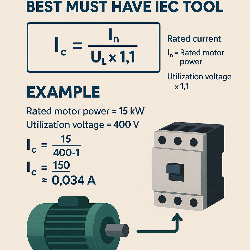
Real-world example 1: Three-phase 15 kW motor at 400 V, DOL start
Problem statement: Select a contactor for a 15 kW, 400 V, 50 Hz, three-phase squirrel-cage induction motor. Data: PF = 0.85, η = 0.90, ambient 35 °C, altitude 200 m, direct-on-line starting, expected 20 starts per hour, utilization AC-3.
Step-by-step solution
- Calculate full-load current:I_FL = P × 1000 / (√3 × V × PF × η)Substitute values: I_FL = 15 × 1000 / (1.732 × 400 × 0.85 × 0.90)Compute denominator: 1.732 × 400 × 0.85 × 0.90 = 530.4 (approx)
I_FL ≈ 15000 / 530.4 ≈ 28.3 A
- Estimate starting current (DOL): use k_st = 6 (typical). I_start = 6 × 28.3 ≈ 170 A.
- Apply safety factor for thermal rating. Base Safety_factor = 1.15. Ambient correction: at 35 °C (<40 °C), no increase. I_required = 28.3 × 1.15 ≈ 32.5 A.
- Lookup contactor rated operational current (Ie) in AC-3. Candidate sizes: 25 A (too small), 32 A (borderline), 40 A recommended.
- Check making capacity: ensure contactor I_making ≥ I_start (170 A). Manufacturer datasheet may state making capacity (peak) 2.5 × Ie for a given short time; verify that for chosen 40 A contactor the making capacity covers 170 A. For instance, 40 A × 2.5 = 100 A (insufficient). Therefore choose a contactor with appropriate making capacity or rating where I_making ≥ 170 A. Many 65 A contactors have higher making capacity and should be considered.
- Consider upgrading to a 65 A AC-3 contactor (Ie = 65 A). Verify: I_required 32.5 A << 65 A, mechanical size supports duty, and making capacity typically exceeds 400 A (check datasheet).
- Verify short-circuit protection coordination: select an MCCB or fuse rated to protect the motor and coordinate with contactor. Ensure interrupting rating at installation point exceeds prospective fault current.
- Finalize selection: 65 A AC-3 contactor, coil voltage selected per control supply (e.g., 230 V AC coil), with a thermal overload relay set to 28.3 A (adjustable 23–32 A depending on model) and auxiliary contacts as required for control logic.
Notes and documentation
- Reference the chosen manufacturer's datasheet to confirm making/breaking capacities and thermal limits at ambient conditions.
- Document IEC utilization category AC-3 compliance and overload settings in the control schematic.
Real-world example 2: Single-phase resistive heating element 5 kW at 230 V
Problem statement: Select a contactor for a 5 kW single-phase resistive load at 230 V with frequent switching (30 operations per hour), utilization AC-1.
Step-by-step solution
- Calculate full-load current:I_FL = P × 1000 / (V × PF × η)
For resistive heater PF ≈ 1, η ≈ 1. So I_FL = 5000 / 230 ≈ 21.74 A.
- Safety and duty: Resistive loads have no motor inrush (k_st ≈ 1), but frequent switching increases electrical endurance demands. Use Safety_factor = 1.1 for ambient and duty. I_required = 21.74 × 1.1 ≈ 23.9 A.
- Select a contactor for AC-1 rated operation. Candidate sizes: 25 A AC-1 contactor is appropriate. Consider mechanical endurance: specify an industrial duty contactor rated for 30 operations per hour and long electrical life (millions of operations) per manufacturer tables.
- Choose coil voltage suitable for control (e.g., 24 V DC coil for PLC control) and include suppression only if required by coil manufacturer recommendations.
- Verify short-circuit protection: fuses or MCCBs sized to protect wiring and contactor; select time-delay fuses if switching high inductive loads exist upstream.
Notes
- Because the heater is resistive (AC-1), making and breaking capacities are simpler than motors; ensure contactor contacts are silver alloy or appropriate for frequent arcing.
- Consider a contactor with forced opening or arc chute if switching inductive or highly capacitive circuits.
Auxiliary considerations: coils, auxiliaries, and protective devices
- Coil voltage and tolerance: IEC contactor coils are available in many voltages (24 V DC, 48 V DC, 110 V DC, 24 V AC, 110 V AC, 230 V AC). Check pick-up and drop-out limits and coil power consumption.
- Coil suppression: for DC coils, use diodes or RC networks compatible with control logic. For AC coils, use RC snubbers or varistors if needed. Verify effects on drop-out time for safety circuits.
- Auxiliary contacts: rated for control voltages and currents; verify AC-15/DC-13 ratings per IEC 60947-5-1 for control switching loads.
- Overload relays: thermal-magnetic or electronic overloads adjustable to motor full-load current; ensure response curve matches motor thermal class and starting frequency.
- Electrical interlocks and mechanical interlocks: use mechanical interlocks for multi-pole contactor assemblies and interlock contactors for reversing starters.
Environmental and installation constraints
- Ingress protection (IP) and enclosure: choose contactor with appropriate IP rating for site (IP20 typical for inside control cabinet, IP65 for harsh environments).
- Vibration and shock: for mobile or seismic applications, select contactors with verified mechanical resilience.
- Pollution degree: IEC pollution degree affects required clearances and creepage distances; install according to local environment (pollution degree 2 typical for industrial indoor).
- EMC: coil suppression can reduce electromagnetic interference; follow EMC directives for control wiring separation from power conductors.
Verification and testing after selection
- Factory Acceptance Tests (FAT): verify coil pick-up/drop-out and contact resistance.
- Site Acceptance Tests (SAT): verify operation under actual supply voltage, verify overload relay tripping at set values, and test interlock and control logic.
- Periodic maintenance: contact wear inspection, contact resistance checks, and coil insulation tests per maintenance schedule.
Normative references and authoritative sources
- IEC 60947-4-1: Low-voltage switchgear and controlgear — contactors and motor-starters — electromechanical contactors and motor-starters. Reference page: https://www.iec.ch/ (search IEC 60947-4-1)
- IEC 60947-1: General rules for low-voltage switchgear and controlgear. https://webstore.iec.ch/
- IEC 60947-5-1: Control circuit devices and switching elements — electromechanical control circuit devices. https://webstore.iec.ch/
- EN 60947 series: European harmonized standards derived from IEC 60947.
- UL 508A: Standard for Industrial Control Panels — relevant for North American installations. https://ul.org/
- Manufacturer technical guides:
- Siemens SIRIUS contactor selection guides — https://new.siemens.com/
- Schneider Electric contactor selection tools — https://www.se.com/
- ABB contactor datasheets and selection guides — https://new.abb.com/
- NEMA ICS standards for North American installations (for compatibility considerations). https://www.nema.org/
Practical tips for implementing a contactor selection calculator as a tool
- Allow user choice of standards (IEC vs NEMA/UL) and map utilization categories accordingly.
- Include manufacturer datasheet links and allow override if a specific series is required.
- Implement ambient and altitude derating curves configurable per manufacturer for accuracy.
- Provide recommended SCCR (short-circuit current rating) checks and protective device coordination guidance.
- Offer exportable reports that capture assumptions, equations, and chosen components for procurement and compliance audits.
SEO and technical content best practices for the article
For maximum international reach, include targeted keywords across headings and content: contactor selection calculator, IEC contactor selection, AC-3 contactor sizing, motor starter calculation, contactor making capacity, overload relay setting, contactor derating. Use schema and structured data in the implementation of the online calculator to expose results for crawlers and machine consumers.
Checklist for engineering teams
- Verify input accuracy: P, V, PF, η, starting method, and duty cycle.
- Confirm utilization category and contactor rated Ie at installation voltage.
- Cross-check making/breaking capacity against inrush and prospective fault conditions.
- Select appropriate coil voltage and suppression methods.
- Verify overload relay and short-circuit protection coordination; document settings.
- Plan for environmental derating and lifecycle maintenance.
Further reading and authoritative links
- IEC webstore (for full standards): https://webstore.iec.ch/
- Siemens SIRIUS contactors technical manuals and selection guides: https://new.siemens.com/global/en/products/automation/systems/industrial-controls.html
- Schneider Electric contactor product pages and sizing tools: https://www.se.com/ww/en/work/products/industrial-automation-control/contactors/
- ABB low-voltage contactors and starters: https://new.abb.com/low-voltage/products/contactors
- National Electrical Code (NEC)/NFPA 70 for North American installations (check local requirements): https://www.nfpa.org/
Final procedural recommendations
- Always consult manufacturer datasheets for making/breaking ratings and thermal derating curves; datasheet values take precedence over tabular approximations.
- Document assumptions and calculations in procurement records to ensure repeatable compliance and easy auditing.
- For critical applications, consider contactor redundancy, remote monitoring of coil current, and predictive maintenance sensors to detect contact wear early.
- Where personnel safety is critical, coordinate with local regulations and certifying bodies; ensure lockout/tagout (LOTO) procedures integrate with chosen contactor control schemes.