Ohm’s Law is a core principle in electrical engineering, explaining voltage, current, and resistance relationships. Understanding these relationships is essential for designing, analyzing, and troubleshooting various electrical and electronic systems efficiently.
Amperes ↔ Resistance (Ω) Calculator
How is resistance calculated?
How is current calculated?
Ohm’s Law Fundamentals
Ohm’s Law is mathematically expressed as:
V=I×R
Where:
- V = Voltage (Volts)
- I = Current (Amperes)
- R = Resistance (Ohms)
This equation indicates that the voltage across a conductor is directly proportional to the current flowing through it, with the resistance being the constant of proportionality.
Common Values Table
Below is a table showcasing common values of voltage, current, and resistance, along with their corresponding power calculations:
| Voltage (V) | Current (I) | Resistance (R) | Power (P = V × I) |
|---|---|---|---|
| 5 V | 0.5 A | 10 Ω | 2.5 W |
| 12 V | 1 A | 12 Ω | 12 W |
| 24 V | 2 A | 12 Ω | 48 W |
| 120 V | 0.1 A | 1200 Ω | 12 W |
| 220 V | 0.2 A | 1100 Ω | 44 W |
These values are typical in various applications, from household electronics to industrial machinery.
Ohm’s Law Formulas and Variable Explanations
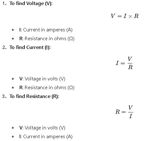
To calculate the unknown in a circuit, Ohm’s Law can be rearranged into three forms:

Each formula is derived from the basic Ohm’s Law equation and is used depending on which two variables are known.
Real-World Applications
1. LED Circuit Design
When designing a circuit to power an LED, it’s essential to calculate the appropriate resistor value to ensure the LED operates within its specified current range.
Example:
- Desired LED current: 20 mA (0.02 A)
- Power supply voltage: 9 V
- LED forward voltage: 2 V
Calculation:

A 350 Ω resistor would limit the current to 20 mA, protecting the LED from excessive current.
2. Power Supply Sizing
In industrial applications, selecting an appropriate power supply requires understanding the total current draw of the system.
Example:
- Total system voltage: 48 V
- Total system resistance: 24 Ω
Calculation:

A power supply rated for at least 48 V and 2 A would be necessary to operate the system efficiently.
Advanced Considerations
While Ohm’s Law is applicable to many circuits, it’s important to note that it assumes a constant resistance. In real-world scenarios, resistance can vary with temperature and material properties. For instance, the resistance of a filament in a light bulb increases as it heats up, which can affect the current and power calculations.
Additionally, in alternating current (AC) circuits, impedance (Z) replaces resistance, and Ohm’s Law is extended to:
V=I×Z
Where impedance accounts for both resistance and reactance (due to inductance and capacitance).
Extensive Common Values Table: Amperes to Resistance
Here’s an expanded and more detailed table including a wide range of commonly used currents and corresponding resistances for practical applications. These values are typical in electronics, household appliances, automotive systems, and industrial machinery:
| Current (A) | Voltage (V) | Resistance (Ω) | Power (W) | Application Example |
|---|---|---|---|---|
| 0.01 | 5 | 500 | 0.05 | Small LED circuits |
| 0.05 | 5 | 100 | 0.25 | Sensor electronics |
| 0.1 | 12 | 120 | 1.2 | Small DC motors |
| 0.2 | 12 | 60 | 2.4 | Arduino peripherals |
| 0.5 | 5 | 10 | 2.5 | High-brightness LEDs |
| 1 | 12 | 12 | 12 | Automotive electronics |
| 2 | 24 | 12 | 48 | Power supplies, small machinery |
| 5 | 24 | 4.8 | 120 | Industrial actuators |
| 10 | 120 | 12 | 1200 | Residential lighting circuits |
| 15 | 220 | 14.67 | 3300 | HVAC small motors |
| 20 | 220 | 11 | 4400 | Industrial equipment |
| 50 | 380 | 7.6 | 19000 | Large power systems |
| 100 | 400 | 4 | 40000 | Heavy machinery circuits |
These values are rounded for clarity, but in actual engineering, precise measurements and safety margins are applied.
Detailed Formula Breakdown
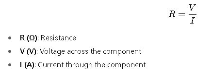
Ohm’s Law allows for calculating resistance when current and voltage are known. The formulas are:
- Resistance from Current and Voltage

Explanation: If a current of 2 A flows through a device with a voltage drop of 12 V, the resistance is R=12/2=6 Ω.
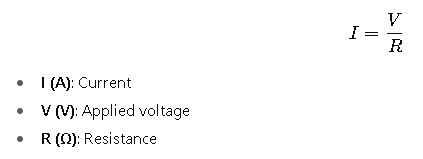
- Current from Voltage and Resistance

Example: A 120 V supply across a 60 Ω resistor results in I=120/60=2 A
- Voltage from Current and Resistance

Example: A 3 A current through a 15 Ω resistor produces V=3×15=45 V
- Power Dissipation

Explanation: This formula is crucial for selecting components to avoid overheating or damage.
Advanced Variable Considerations
- Temperature Coefficient of Resistance: Resistance often changes with temperature. For example, copper has a positive temperature coefficient (~0.00393 Ω/Ω/°C).
- R_T: Resistance at temperature T
- R_0: Resistance at reference temperature
- α: Temperature coefficient
- ΔT: Temperature difference
- Non-linear Devices: Devices like semiconductors or incandescent bulbs do not follow linear Ohm’s Law; their resistance changes with voltage, current, or temperature.
- AC Circuits: In alternating current systems, resistance is replaced by impedance (Z), combining resistance (R) and reactance (X):
- X: Reactance due to inductors and capacitors
Real-World Case Studies
Case Study 1: Automotive Headlight Circuit
Scenario: A 12 V car battery powers a headlight designed for 2 A.
Solution:

3.Implication: A resistor with at least 24 W rating or the headlight filament must handle this power.
Outcome: Ensures optimal brightness without damaging the headlight.
Case Study 2: Industrial Control Circuit
Scenario: A control system operates at 48 V, requiring a current of 5 A for a solenoid actuator.
Solution:

3.Practical considerations:
- Use a resistor or device rated for >240 W.
- Ensure wiring supports 5 A to avoid overheating.
Outcome: System operates efficiently, minimizing energy loss and preventing failures.

