This article details conduit thermal movement calculation methods for PVC and metallic conduit systems accurately.
Engineers require precise gap, expansion allowance, and restraint strategies to prevent mechanical failure and hazards.
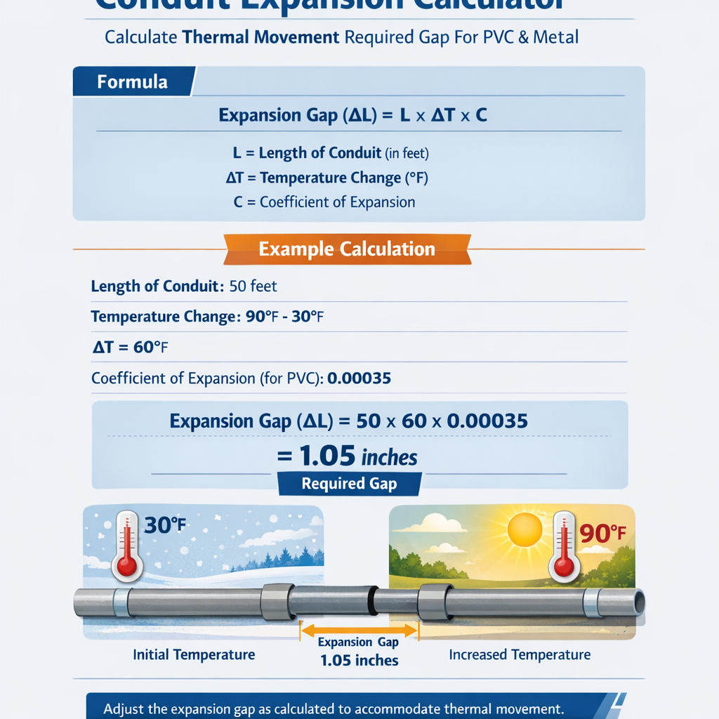
Conduit Expansion Calculator – Thermal Movement and Expansion Gap for PVC and Metal
Background and scope of conduit thermal movement
Thermal movement of electrical conduits is the linear expansion or contraction of conduit material caused by differential temperature. Conduit expansion is relevant for both buried and exposed runs, long-horizontal spans, and systems where conduits are constrained by fittings, building structure, or abrupt transitions between materials (PVC-to-metal, aluminium-to-steel, etc.). Understanding required gaps and expansion allowances prevents buckling, joint separation, conduit distortion, and damage to junctions or cable insulation. This article supplies a precise calculation basis, worked examples, and practical design recommendations for PVC and common metal conduits, with normative references and external authoritative links.Physical principle and basic calculation approach
Thermal linear movement for a uniform, unconstrained member is computed from the linear thermal expansion relation:ΔL = α × L × ΔT
- ΔL = linear change in length (m or mm)
- α = coefficient of linear thermal expansion (1/°C or 1/°F)
- L = original length between fixed points (m or mm)
- ΔT = temperature change (°C or °F) applied to the element
- Determination of the worst-case ΔT range (site + ambient extremes + solar gain).
- Selection of α for the material and conditioning for installation state.
- Definition of L as the distance between anchors or fixed restraints.
- Assignment of required joint / gap size including tolerance and safety margin.
Material properties: coefficients and common values
Below is a comprehensive table of common conduit materials and their representative coefficients of linear thermal expansion (α). Values are conservative engineering typical values; consult manufacturer data for precise design and the project-specific temperature range.| Material | Typical α (×10^-6 /°C) | Typical α (×10^-6 /°F) | Notes / Typical temperature behaviour |
|---|---|---|---|
| Rigid PVC (uPVC) | 70 | 39 | Rigid PVC conduit (Schedule 40/80). α varies with formulation; use manufacturer data. |
| CPVC | 65 | 36 | Chlorinated PVC; slightly lower α than PVC; used for hot applications. |
| HDPE | 150 | 83 | Very high expansion; critical for long buried runs and above-ground installations. |
| Carbon Steel (galvanized conduit) | 12 | 6.7 | Standard metallic conduit (EMT/RMC/IMC); low α compared to plastics. |
| Stainless Steel | 17 | 9.4 | Higher α than carbon steel; consider differential expansion at couplings. |
| Copper | 16.8 | 9.3 | Used for specific conductive/performance applications; moderate α. |
| Aluminium | 23 | 12.8 | High α among metals; pay attention where aluminium conduits interface with steel or masonry. |
Typical movement per unit length — quick-reference table
Engineers commonly need quick conversion of expansion per metre for unit ΔT. The table below presents ΔL per metre for ΔT = 1°C and ΔT = 40°C, which are practical increments for design checks.| Material | α (1/°C) | ΔL per m @ ΔT = 1°C (mm/m) | ΔL per m @ ΔT = 40°C (mm/m) | ΔL per 10 m @ ΔT = 40°C (mm) |
|---|---|---|---|---|
| Rigid PVC | 0.000070 | 0.070 | 2.80 | 28.0 |
| CPVC | 0.000065 | 0.065 | 2.60 | 26.0 |
| HDPE | 0.000150 | 0.150 | 6.00 | 60.0 |
| Carbon Steel | 0.000012 | 0.012 | 0.48 | 4.8 |
| Stainless Steel | 0.000017 | 0.017 | 0.68 | 6.8 |
| Copper | 0.0000168 | 0.0168 | 0.67 | 6.7 |
| Aluminium | 0.000023 | 0.023 | 0.92 | 9.2 |
Calculation method and formula application
Step-by-step method:- Define the span length L between fixed anchors or structural restraints.
- Select the correct α for conduit material (from the table or manufacturer’s data).
- Estimate the worst-case ΔT: difference between installation/reference temperature and maximum operating temperature expected.
- Compute ΔL using ΔL = α × L × ΔT.
- Design joint gaps and expansion fittings so that the sum of free gaps and permitted movement is greater than ΔL (include safety margins and tolerance).
ΔL (mm) = α (1/°C) × L (m) × ΔT (°C) × 1000
Lmax (m) = G_total (mm) / (α × ΔT × 1000)
Variable definitions and typical values
- α — see Material table; typical values: PVC 70 ×10^-6/°C; steel 12 ×10^-6/°C.
- L — length between effective fixed anchors. Use construction drawings; if continuous fixed support exists, identify true fixed points.
- ΔT — design temperature range. Example: if conduit installed at 20°C but can reach 60°C in sun, ΔT = 40°C.
- ΔL — expected movement. Add margin: ΔL_design = ΔL × (1 + safety_factor). Safety factor typical 0.1 (10%).
- G_required — required gap or expansion joint travel. G_required ≥ ΔL_design.
Design allowances, joints, and anchoring best practices
Thermal design for conduit systems involves not just calculation of movement but the mechanical detailing to accommodate it:- Anchors (fixed points): designate at least one fixed anchor to accept thermal loads; downstream anchors should allow relative movement.
- Movement joints: use factory expansion joints or slip couplings for PVC and metal conduits especially where ΔL exceeds installation tolerances.
- Offset loops: provide loops or offsets to absorb axial movement where joints are not feasible.
- Differential material interfaces: where PVC joins metal, provide transitional couplings that allow slip or incorporate expansion fitting to accommodate different α values.
- Support spacing: for PVC and HDPE, support spacing must allow axial movement and avoid embedding in rigid supports that restrain thermal expansion.
- Buried vs exposed runs: buried conduits have reduced temperature swings (soil damping) but still require allowance for seasonal ΔT and long-length effects.
Engineering rules of thumb
- PVC: expect ~2.8 mm/m for ΔT = 40°C. For a 10 m run, ΔL ≈ 28 mm — significant and requires expansion fittings or slack.
- Steel conduit: expect ~0.48 mm/m for ΔT = 40°C; across 10 m ΔL ≈ 4.8 mm, manageable with small gaps or slip couplings.
- HDPE: very high expansion; route with loops or provide expansion joints frequently for above-ground runs.
Worked examples (real-case calculations)
Below are complete worked examples showing calculation steps, gap sizing, and selection logic for real scenarios.Example 1 — PVC conduit, exterior exposed run
Problem statement:- Material: Rigid PVC conduit (α = 70 ×10^-6 /°C).
- Length between fixed supports (L): 30.0 m continuous run attached to rooftop supports.
- Installation (reference) temperature: 20°C. Maximum expected operating temperature on rooftop (solar heated): 65°C. So ΔT = 45°C.
- Design safety factor: 10% (0.10).
- Goal: compute ΔL, and recommend minimum total gap and possible mitigation.
ΔL_raw = α × L × ΔT
α = 70 × 10^-6 /°C = 0.000070 /°C
ΔL_raw (m) = 0.000070 × 30.0 × 45 = 0.0945 m
ΔL_raw (mm) = 0.0945 × 1000 = 94.5 mm
ΔL_design = ΔL_raw × (1 + 0.10) = 94.5 × 1.10 = 103.95 mm ≈ 104.0 mm
- Total axial expansion expected = 104 mm. If using two expansion gaps (one at each fixed end allowing movement toward the middle), allocate 52 mm gap each side.
- Recommended action: provide an expansion coupling or slip joint with travel ≥ 52 mm at one end, or provide two expansion fittings each with ≥ 52 mm travel depending on mechanical arrangement.
- Alternatively, redesign anchor strategy: reduce anchored run length by adding intermediate anchor points or provide change-of-material transition with sliding allowances.
- If using single expansion joint at mid-run: joint travel must accommodate full 104 mm.
- 94.5 mm raw movement over 30 m is substantial for PVC; typical commercial PVC expansion couplings may provide limited travel — verify manufacturer specifications or split the run.
- Consider routing offsets (S-bends) to absorb some axial movement if expansion joints are not feasible due to maintenance or space constraints.
Example 2 — Galvanized steel conduit (EMT) inside an industrial facility
Problem statement:- Material: Galvanized steel conduit (α = 12 ×10^-6 /°C).
- Length between building expansion anchors: 50.0 m run inside an industrial shed, ambient temperature in winter can drop to -20°C and in summer can reach +50°C. Assume reference (installation) temperature 20°C, worst-case ΔT = 30°C (heating) to +30°C (cooling) — the largest magnitude is 50°C change from -20 to +30 (but be rigorous: consider absolute extremes). For conservative design take ΔT = 70°C (from -20°C to +50°C) if conduit will experience full environmental extremes.
- Use conservative ΔT = 70°C for safety.
- Design safety factor: 10%.
α = 12 × 10^-6 /°C = 0.000012 /°C
ΔL_raw (m) = 0.000012 × 50.0 × 70 = 0.042 m
ΔL_raw (mm) = 0.042 × 1000 = 42 mm
ΔL_design = 42 × 1.10 = 46.2 mm
- Total axial movement ~46.2 mm. For a metallic conduit this is significant but smaller than PVC of similar length.
- Recommended: incorporate slip couplings or expansion fittings capable of at least 50 mm travel, or break the run with an engineered expansion joint every 25–30 m to reduce movement per segment.
- If creating two segments of 25 m, compute movement per segment: ΔL_segment = 0.000012 × 25 × 70 × 1000 = 21 mm (raw), with safety ~23 mm. Expansion joints with ~25 mm travel would suffice per segment.
- Galvanized steel slip couplings and expansion fittings are available with stated travel; choose a product rated for axial travel and for electrical continuity as required by codes.
- Balance electrical bonding and mechanical sliding: sliding joints must maintain electrical continuity using bonding jumpers or specialized expansion coupling designs.
Example 3 — Mixed-material transition: PVC to steel over 12 m
Problem statement:- Segment A: 8.0 m PVC (α = 70 ×10^-6 /°C).
- Segment B: 4.0 m steel (α = 12 ×10^-6 /°C).
- Temperature increase ΔT = 35°C (worst expected).
- Find differential movement and required allowance at the transitional coupling.
ΔL_PVC (mm) = 0.000070 × 8.0 × 35 × 1000 = 19.6 mm
ΔL_steel (mm) = 0.000012 × 4.0 × 35 × 1000 = 1.68 mm
Total ΔL_total = 19.6 + 1.68 = 21.28 mm
ΔL_diff = ΔL_PVC - ΔL_steel = 19.6 - 1.68 = 17.92 mm
- The PVC end will try to expand approximately 18 mm more than the steel end for the given ΔT and segment lengths. Provide a transition coupling that allows axial sliding of at least 20 mm plus safety margin (10%) — specify ~22 mm sliding capacity.
- Bonding: maintain electrical continuity across sliding joints with flexible bonding jumpers sized per code.
- Consider limiting PVC run lengths before transition or using slip sleeves to absorb differential movement.
Tables for gap selection and maximum fixed spacing examples
The following table shows Lmax (maximum length between anchors) for given total allowed gap (G_total) and ΔT assumptions for PVC and steel. Formula used:Lmax (m) = G_total (mm) / (α × ΔT × 1000)
| Conduit Material | α (1/°C) | ΔT (°C) | G_total (mm) | Lmax (m) |
|---|---|---|---|---|
| Rigid PVC | 0.000070 | 40 | 50 | 50 / (0.000070 × 40 × 1000) = 17.86 m |
| Rigid PVC | 0.000070 | 40 | 100 | 35.71 m |
| Carbon Steel | 0.000012 | 40 | 50 | 50 / (0.000012 × 40 × 1000) = 104.17 m |
| Carbon Steel | 0.000012 | 70 | 50 | 59.52 m |
| HDPE | 0.000150 | 40 | 50 | 8.33 m |
Practical installation notes and complications
Engineers must consider:- Initial installation temperature: if conduit is installed cold and will heat up, expansion will be positive; if installed hot and later cooled, contraction occurs — both need consideration to avoid pull-out or slack.
- Creep and long-term dimensional changes particularly in plastics (PVC and HDPE) can produce additional movement under sustained loads.
- Thermal cycling causes fatigue at joints. Select fittings rated for cyclic axial movement when systems will experience frequent temperature swings.
- Electrical continuity: metallic conduits often serve grounding/bonding functions. Expansion couplings should either maintain conductivity or be augmented with bonding jumpers sized per code (e.g., NEC requirements for bonding conductors).
- Corrosion and environmental degradation may alter mechanical performance of joints; select materials and coatings accordingly.
Recommended checklist for using a conduit expansion calculator in design
When using a calculator or performing manual calculations, verify:- Material α value is from manufacturer or validated reference.
- Reference and maximum temperatures reflect worst-case environmental exposure (solar, process heat, buried vs exposed).
- Length L is the effective distance between true fixed anchors; supports that allow sliding are not anchors.
- Account for differential expansion where mixed materials are used.
- Specify expansion fittings with adequate axial travel and electrical bonding as required.
- Include installation instructions to ensure anchors and gaps are set at commissioning temperature reference.
Normative references and external authoritative sources
Designers should consult the following standards and authoritative guidance for installation practice, testing, and product data:- NFPA 70, National Electrical Code (NEC). For bonding, grounding, and conduit installation requirements: https://www.nfpa.org/ (requires subscription for full text).
- BS EN 61386 series — Conduit systems for cable management (European standard for conduit systems): https://www.en-standard.eu/bs-en-61386-1-2011-conduit-systems-for-cable-management/
- ASTM standards for plastic materials and piping (e.g., material property standards): https://www.astm.org/
- NIST material data and references for coefficients of thermal expansion: https://www.nist.gov/
- Engineering Toolbox — reference values for thermal expansion of materials: https://www.engineeringtoolbox.com/linear-expansion-coefficients-d_95.html
- Manufacturer technical datasheets: e.g., Charlotte Pipe, JM Eagle for PVC/HDPE conduit specifications (consult specific product pages for CTE values).
Implementation for a conduit expansion calculator tool
If building a calculator, include the following inputs and outputs: Inputs:- Material selection (drop-down with standard α values and option for custom α).
- Length between anchors (L) in m.
- Reference temperature (°C) and maximum/minimum expected temperatures to compute ΔT.
- Number and location of anchors (to split segments).
- Desired safety factor or tolerance.
- Gap allocation strategy (single end, both ends, distributed expansion joints).
- ΔL (raw) in mm and m.
- ΔL with safety factor.
- Recommended minimum gap per end and total gap required.
- Suggested maximum L for given gap and ΔT.
- Notes on differential expansion if mixed materials present.
- Warn if ΔL exceeds typical available expansion fitting stroke.
- Flag differential movement larger than a threshold (e.g., >10 mm) for mixed-material transitions.
- Provide guidance text for electrical continuity or bonding when metallic conduits have sliding joints.
Conclusion and final engineering recommendations
For accurate conduit thermal movement design:- Calculate ΔL with conservative α and ΔT values, convert units consistently, and add a safety factor.
- Provide expansion joints, slip couplings, or slack and offsets according to the computed ΔL and available product travel.
- Pay special attention to plastic conduits (PVC, HDPE) because their α values are an order of magnitude higher than metals, causing substantial movement on long runs.
- Where materials change (PVC-to-metal), design the transitional couplings to absorb differential movement and ensure electrical continuity by bonding jumpers or conductive joint designs.
- Document the installation reference temperature and commissioning procedures so future maintenance and modifications preserve the designed expansion allowances.
- NFPA 70: National Electrical Code. https://www.nfpa.org/
- Engineering Toolbox: Linear expansion coefficients for common materials. https://www.engineeringtoolbox.com/linear-expansion-coefficients-d_95.html
- NIST material properties: https://www.nist.gov/
- BS EN 61386 series: Conduit systems for cable management (purchase/abstract at national standards bodies).
- Manufacturer technical datasheets for PVC conduit (examples: Charlotte Pipe, JM Eagle) — consult product pages for exact α and installation guidance.
- Provide a downloadable spreadsheet implementing the calculator formulas and tables shown.
- Generate specific calculations for a project dataset (provide lengths, materials, and temperature ranges).
- Produce annotated drawings showing anchor locations and expansion joint placements for the worked examples.