I_max = k × S ÷ √t · S_min = I × √t ÷ k · I²t = k²S²📊 k-Factor Reference (IEC 60364)
| Material | Insulation | k | Temp range |
|---|---|---|---|
| Copper | XLPE / EPR | 143 | 90→250 °C |
| Copper | PVC | 115 | 70→160 °C |
| Aluminum | XLPE / EPR | 94 | 90→250 °C |
| Aluminum | PVC | 76 | 70→160 °C |
The conductor short-circuit capacity calculator determines whether a cable can survive a fault without its insulation exceeding its thermal limit. The method comes from IEC 60364-5-54 (also detailed in IEC 60949) and uses the adiabatic equation I²t = k²S², where I is the fault current, t is the clearing time, k is a material/insulation constant, and S is the conductor cross-section. If the prospective I²t exceeds k²S², the conductor will overheat and the insulation may be permanently damaged—or worse, start a fire.
Every cable sizing exercise in an IEC-compliant installation must include this short-circuit withstand check in addition to current-carrying capacity (ampacity) and voltage-drop calculations. The calculator above lets you find either the maximum fault current a conductor can handle or the minimum cross-section required for a given fault level. Read on for the complete IEC formulas, k-factor tables, and six fully worked examples covering real installations.
Short-Circuit Capacity Table — Common Conductor Sizes (t = 1 s)
The table below shows the maximum symmetrical short-circuit current each standard IEC conductor size can withstand for a 1-second fault duration, for the four most common material/insulation combinations. All values are calculated with I_max = k × S ÷ √t; for 1 second, √t = 1, so I_max = k × S.
| Size (mm²) | Cu/XLPE k=143 (kA) | Cu/PVC k=115 (kA) | Al/XLPE k=94 (kA) | Al/PVC k=76 (kA) |
|---|---|---|---|---|
| 1.5 | 0.21 | 0.17 | 0.14 | 0.11 |
| 2.5 | 0.36 | 0.29 | 0.24 | 0.19 |
| 4 | 0.57 | 0.46 | 0.38 | 0.30 |
| 6 | 0.86 | 0.69 | 0.56 | 0.46 |
| 10 | 1.43 | 1.15 | 0.94 | 0.76 |
| 16 | 2.29 | 1.84 | 1.50 | 1.22 |
| 25 | 3.58 | 2.88 | 2.35 | 1.90 |
| 35 | 5.01 | 4.03 | 3.29 | 2.66 |
| 50 | 7.15 | 5.75 | 4.70 | 3.80 |
| 70 | 10.01 | 8.05 | 6.58 | 5.32 |
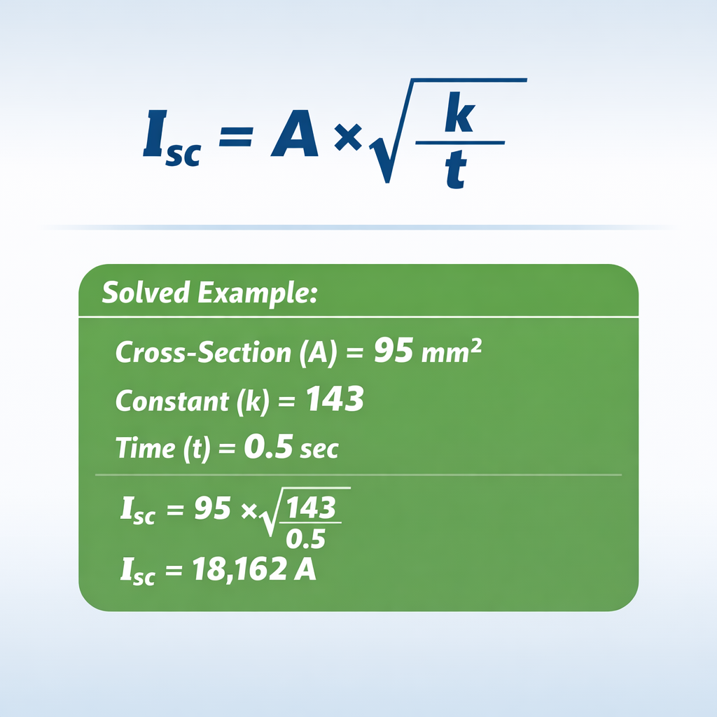
| 95 | 13.59 | 10.93 | 8.93 | 7.22 |
| 120 | 17.16 | 13.80 | 11.28 | 9.12 |
| 150 | 21.45 | 17.25 | 14.10 | 11.40 |
| 185 | 26.46 | 21.28 | 17.39 | 14.06 |
| 240 | 34.32 | 27.60 | 22.56 | 18.24 |
| 300 | 42.90 | 34.50 | 28.20 | 22.80 |
For fault durations other than 1 second, divide the values above by √t. For example, a 95 mm² Cu/XLPE cable at t = 0.5 s can withstand 13.59 ÷ √0.5 = 13.59 ÷ 0.707 = 19.21 kA. Shorter clearing times dramatically increase the withstand capacity—this is one of the key reasons to use fast-acting protection devices.
IEC Adiabatic Formula — Step by Step
The IEC method assumes the fault is so brief that no heat escapes the conductor during the event (adiabatic condition). All the energy I²t heats the conductor from its initial operating temperature to the maximum permissible temperature of the insulation.
The Master Equation
Where: I = prospective short-circuit current (A rms) · t = fault clearing time (s) · k = material/insulation constant · S = conductor cross-section (mm²).
Find Maximum Fault Current for a Given Conductor
Use this when you already have the cable installed and want to verify it can survive the prospective fault level at that point in the network.
Quick example: 95 mm² Cu/XLPE, t = 1 s → I_max = 143 × 95 ÷ 1 = 13,585 A (13.59 kA).
Find Minimum Conductor Size for a Given Fault Level
Use this when designing a new installation: you know the prospective fault current and the protection clearing time, and you need to select a cable that will survive.
Quick example: 25 kA fault, t = 0.5 s, Cu/XLPE → S_min = 25,000 × √0.5 ÷ 143 = 25,000 × 0.707 ÷ 143 = 123.6 mm² → select 150 mm².
The k Constant
The k factor captures the thermal properties of both the conductor material (copper or aluminum) and the insulation type (which sets the allowable final temperature). Higher k means the conductor can absorb more energy per mm² before the insulation is damaged. The values are tabulated in IEC 60364-5-54, Table 43A, and reproduced in the section below.
k-Factor Comparison — Materials & Insulation Types
Choosing the right k value is critical—using the wrong constant can undersize or oversize a conductor. The table below compares the most common combinations for phase conductors and the additional values used for protective (earth) conductors per IEC 60364-5-54.
| Conductor | Insulation | Initial Temp (°C) | Final Temp (°C) | k (phase) | k (PE in cable) |
|---|---|---|---|---|---|
| Copper | XLPE / EPR | 90 | 250 | 143 | 143 |
| Copper | PVC ≤ 300 mm² | 70 | 160 | 115 | 115 |
| Copper | Mineral (bare sheath) | 70 | 200 | 135 | — |
| Aluminum | XLPE / EPR | 90 | 250 | 94 | 94 |
| Aluminum | PVC ≤ 300 mm² | 70 | 160 | 76 | 76 |
| Copper | Bare (not in cable) | 30 | 200 | — | 159 |
| Copper | Bare (not in cable) | 30 | 300 | — | 228 (bonding) |
Note that copper with XLPE insulation (k = 143) can handle 52 % more fault energy per mm² than aluminum with XLPE (k = 94). This is why copper cables dominate in applications where short-circuit levels are high and space is limited, even though aluminum is lighter and cheaper per meter.
Minimum Conductor Size from Fault Current
The inverse calculation—finding the smallest conductor that survives a given fault—is the one most frequently needed during design. The table below gives the minimum cross-section for several common fault levels and clearing times, using Cu/XLPE (k = 143).
| Fault (kA) | t = 0.1 s | t = 0.2 s | t = 0.5 s | t = 1.0 s | t = 3.0 s |
|---|---|---|---|---|---|
| 6 | 1.5→4 | 4→6 | 6→10 | 10→16 | 25→35 |
| 10 | 4→4 | 6→10 | 10→16 | 16→25 | 35→50 |
| 16 | 4→6 | 10→10 | 16→25 | 35→35 | 50→70 |
| 25 | 6→10 | 10→16 | 25→35 | 50→50 | 95→95 |
| 40 | 10→10 | 16→25 | 35→50 | 70→95 | 150→150 |
| 50 | 10→16 | 25→25 | 50→50 | 95→95 | 185→185 |
Format: calculated S_min → next standard IEC size. Always round up to the next available commercial cross-section. For cable sizing in related calculations, see our AWG to mm² equivalences and AWG to mm² calculator.
6 Solved Examples — Conductor Short-Circuit Capacity
Example 1 — Verify 10 mm² Cu/PVC for a 6 kA Panel (t = 0.2 s)
Data: S = 10 mm², k = 115, t = 0.2 s
Formula: I_max = k × S ÷ √t
Calculation: I_max = 115 × 10 ÷ √0.2 = 1,150 ÷ 0.4472 = 2,572 A (2.57 kA)
The panel has a 6 kA prospective fault level but the cable can only withstand 2.57 kA. This cable is undersized for short-circuit protection. Minimum size needed: S = 6,000 × 0.4472 ÷ 115 = 23.3 mm² → use 25 mm².
Example 2 — Size a Motor Feeder for 25 kA (t = 0.5 s, Cu/XLPE)
Data: I = 25 kA, k = 143, t = 0.5 s
Formula: S_min = I × √t ÷ k
Calculation: S_min = 25,000 × √0.5 ÷ 143 = 25,000 × 0.7071 ÷ 143 = 123.6 mm² → use 150 mm²
A 150 mm² Cu/XLPE cable is the minimum to survive the 25 kA fault. If the motor feeder also needs to carry 200 A continuously, 150 mm² provides adequate ampacity as well (IEC 60364-5-52 rates it at ~275 A in trefoil).
Example 3 — Check 240 mm² Al/XLPE at 40 kA (t = 1 s)
Data: S = 240 mm², k = 94, t = 1 s
Formula: I_max = k × S ÷ √t
Calculation: I_max = 94 × 240 ÷ 1 = 22,560 A (22.56 kA)
The 240 mm² Al/XLPE cable can only handle 22.56 kA, but the fault level is 40 kA. This cable fails the short-circuit check. Minimum Al/XLPE size: S = 40,000 ÷ 94 = 425.5 mm² → no single cable suffices; use parallel 2 × 240 mm² runs or switch to copper (Cu/XLPE needs S = 40,000 ÷ 143 = 279.7 mm² → use 300 mm²).
Example 4 — Effect of Clearing Time on 95 mm² Cu/XLPE
Data: S = 95 mm², k = 143
Results by time:
t = 0.1 s → I_max = 143 × 95 ÷ 0.3162 = 42.96 kA
t = 0.5 s → I_max = 143 × 95 ÷ 0.7071 = 19.21 kA
t = 1.0 s → I_max = 143 × 95 ÷ 1.0 = 13.59 kA
t = 3.0 s → I_max = 143 × 95 ÷ 1.7321 = 7.84 kA
Faster protection dramatically increases withstand capacity. A 95 mm² cable with a 100 ms breaker can survive 43 kA, but with a 3 s fuse it only handles 7.8 kA. This is why current-limiting breakers and fast fuses are critical in high fault-level installations.
Example 5 — Copper vs. Aluminum at 120 mm² (t = 1 s)
Data: S = 120 mm², t = 1 s
Cu/XLPE (k=143): I_max = 143 × 120 = 17.16 kA
Al/XLPE (k=94): I_max = 94 × 120 = 11.28 kA
Copper handles 52 % more fault current than aluminum at the same cross-section. To match copper’s 17.16 kA capacity with aluminum, you would need S = 17,160 ÷ 94 = 182.6 mm² → a 185 mm² Al/XLPE cable. This trade-off between material cost and cable tray space is a core decision in every industrial design.
Example 6 — Protective Earth (PE) Conductor Sizing
Data: I = 15 kA, t = 0.4 s, bare copper PE (k = 159)
Formula: S_min = I × √t ÷ k
Calculation: S_min = 15,000 × √0.4 ÷ 159 = 15,000 × 0.6325 ÷ 159 = 59.7 mm² → use 70 mm²
The protective earth conductor must survive the same fault as the phase conductor so that the protective device can clear the fault safely. Using k = 159 (bare copper PE, not in contact with cable insulation, initial 30 °C → final 200 °C from IEC 60364-5-54 Table 54.4) ensures the PE is thermally rated for the disconnection time of the upstream breaker.
Practical Applications of Conductor Short-Circuit Capacity
The IEC adiabatic check is not an academic exercise—it is a mandatory compliance step in every IEC 60364 installation. Here are the situations where the conductor short-circuit capacity calculator is essential.
New cable sizing: After selecting a cable based on ampacity (IEC 60364-5-52) and voltage drop, you must verify that the prospective fault current at the point of installation does not exceed the cable’s I²t withstand. If it does, you either upsize the cable or install a faster protective device. This check applies to every circuit—from a 1.5 mm² lighting branch to a 300 mm² main busbar tie.
Existing installation audits: When a transformer is upgraded or a new generator is paralleled, the fault level at downstream panels increases. You need to re-verify every cable against the new fault level. Our Fault Current (AIC) Calculator helps determine the prospective fault current at each panel, and then this calculator verifies each feeder cable.
Protective-device coordination: The cable’s I²t withstand sets an upper boundary on how slowly a breaker or fuse can clear a fault. If the cable can only survive I²t = 20,449,000 A²s (95 mm² Cu/XLPE at 1 s), the breaker’s total clearing I²t must be below that threshold at every fault level within its operating range. See our Arc Flash Calculator for related protection analysis.
Earth-fault loop impedance verification: The minimum PE conductor size is calculated using the same adiabatic formula, ensuring the earth path can carry the fault current long enough for the protective device to trip. For balanced vs. unbalanced load scenarios, see our Balanced & Unbalanced Load Calculation.
Quick Equivalencies — Common Short-Circuit Queries
IEC 60949
Short-circuit thermal limits of cables
IEC 60949 provides detailed methodology for calculating cable short-circuit temperature rise. The simplified adiabatic equation I²t = k²S² from IEC 60364-5-54 is derived from this standard.
I²t = k²S²
Adiabatic equation
The core relationship. If the prospective fault I²t exceeds k²S², the conductor insulation will be thermally damaged. Rearranged: I_max = kS/√t or S_min = I√t/k.
k = 143 (Cu/XLPE)
Most common k factor
Copper conductor with cross-linked polyethylene insulation, initial 90 °C → final 250 °C. The default for modern industrial and utility cable installations worldwide.
k = 115 (Cu/PVC)
Copper with PVC
Initial 70 °C → final 160 °C. Common in commercial and residential wiring up to 300 mm². Lower k than XLPE because PVC has a lower maximum temperature.
k = 94 (Al/XLPE)
Aluminum with XLPE
34 % lower capacity per mm² than copper/XLPE. Used in cost-sensitive installations where cable tray space permits the larger conductor sizes needed.
k = 76 (Al/PVC)
Aluminum with PVC
The lowest k factor of the four standard combinations. Requires the largest conductor sizes for a given fault level. Common in older residential overhead service drops.
95 mm² Cu/XLPE at 1 s
13.59 kA
A commonly referenced benchmark. At 0.5 s it handles 19.21 kA, and at 0.1 s it handles 42.96 kA—demonstrating the huge benefit of fast protection.
Adiabatic vs. Non-Adiabatic
Adiabatic is conservative
The adiabatic method assumes zero heat dissipation during the fault. For faults over 5 s, non-adiabatic methods (IEC 60949 Annex A) allow credit for heat loss, reducing the required conductor size.
Frequently Asked Questions — Conductor Short-Circuit Capacity
What is the adiabatic equation for cable short-circuit?
I²t = k²S². This equation states that the thermal energy the conductor absorbs during a fault (I²t) must not exceed the energy its insulation can tolerate (k²S²). It comes from IEC 60364-5-54 and IEC 60949.
What does the k factor depend on?
Two things: the conductor material (copper or aluminum) and the insulation type (which sets the initial and final permissible temperatures). For example, copper with XLPE has k = 143 because XLPE tolerates 250 °C, while PVC only tolerates 160 °C, giving k = 115.
How do I find the maximum fault current a cable can handle?
Use I_max = k × S ÷ √t. A 50 mm² Cu/XLPE cable (k = 143) with a 0.5 s clearing time handles I_max = 143 × 50 ÷ 0.707 = 10,113 A = 10.11 kA.
How do I find the minimum conductor size for a given fault level?
Use S_min = I × √t ÷ k. For a 20 kA fault with t = 1 s and Cu/XLPE: S_min = 20,000 × 1 ÷ 143 = 139.9 mm² → select the next standard size: 150 mm².
Why does faster protection allow smaller cables?
Because S_min is proportional to √t. Halving the clearing time reduces the required cross-section by a factor of √2 ≈ 1.414. A 100 ms breaker lets you use a cable roughly 3.16 times smaller than a 1 s breaker for the same fault current.
Is the adiabatic method valid for long fault durations?
It is conservative for faults up to about 5 seconds. Beyond that, the conductor actually dissipates some heat to the surrounding insulation and environment, so the adiabatic method overstates the temperature rise. For durations above 5 s, IEC 60949 Annex A provides a non-adiabatic correction.
Does this calculation apply to protective (earth) conductors?
Yes. IEC 60364-5-54 Section 543 requires the PE conductor to survive the fault current for the disconnection time of the protective device. The formula is the same: S_min = I × √t ÷ k, but the k value may differ (e.g., k = 159 for bare copper PE not in contact with insulation).
What is the difference between prospective and let-through I²t?
Prospective I²t assumes the fault current flows for the full clearing time without current limitation. Let-through I²t is the actual energy a current-limiting device (fuse or breaker) allows through. If the device’s let-through I²t is below k²S², the cable is protected even if the prospective I²t exceeds it.
Why is copper better than aluminum for short-circuit capacity?
Copper has higher thermal conductivity, higher specific heat per unit volume, and lower resistivity. This gives it a higher k factor (143 vs. 94 for XLPE insulation), meaning each mm² of copper can absorb 52 % more fault energy than aluminum before reaching the insulation’s thermal limit.
Can I use this calculator for medium-voltage cables?
Yes, the adiabatic formula is universal. However, MV cables have different insulation systems (e.g., XLPE with semi-conductive screens) and the k values may differ slightly. Consult the cable manufacturer’s data sheet for the exact k value. The standard IEC phase-conductor k values are suitable for most practical MV calculations.
What happens if the cable fails the short-circuit check?
You have three options: upsize the cable to increase S, install a faster protective device to reduce t, or use a current-limiting device (HRC fuse or current-limiting MCCB) whose let-through I²t is below k²S². The most economical solution depends on the specific installation.
Where do I find the prospective fault current for my installation?
From a short-circuit study (per IEC 60909) or from the utility’s fault-level declaration at the point of supply. Our Fault Current (AIC) Calculator can help estimate it from transformer data.
Related Calculators
Explore more power-system engineering tools on our site:
- Fault Current (AIC) Calculator — determine available fault current at panels.
- Arc Flash Calculator (IEEE 1584) — compute incident energy for PPE selection.
- AWG to mm² Equivalences — wire-size cross-reference for international projects.
- AWG to mm² Calculator (IEC/NEMA) — convert wire gauges with conductor data.
- Amps to kW Calculator — convert motor current to electrical power.
- Balanced & Unbalanced Load Calculation — three-phase load distribution.
- Transformer kVA Sizing Calculator — size transformers from demand load.