Electrical engineers and technicians often face difficulties converting watts into volt-amperes for accurate system sizing. Watts indicate real power, volt-amperes measure apparent power; calculators ensure correct UPS, generator, and distribution equipment.
Watts (W) → Volt-Amps (VA)
Conversion Tables: Watts to VA at Common Power Factors
The conversion between watts and VA depends on the power factor (PF), which is the ratio of real power to apparent power:
Since the power factor varies depending on the type of load (resistive, inductive, capacitive, or mixed), tables are often the fastest way to approximate conversions. Below are extensive tables for common scenarios.
Table 1: Conversion at Power Factor 1.0 (Ideal Resistive Load)
When PF = 1, real power equals apparent power, meaning watts = VA.
| Watts (W) | Volt-Amperes (VA) |
|---|---|
| 50 W | 50 VA |
| 100 W | 100 VA |
| 200 W | 200 VA |
| 300 W | 300 VA |
| 400 W | 400 VA |
| 500 W | 500 VA |
| 750 W | 750 VA |
| 1000 W | 1000 VA |
| 1500 W | 1500 VA |
| 2000 W | 2000 VA |
| 3000 W | 3000 VA |
| 5000 W | 5000 VA |
| 10000 W | 10000 VA |
Table 2: Conversion at Power Factor 0.9 (Common for IT Equipment)
| Watts (W) | Volt-Amperes (VA) |
|---|---|
| 50 W | 56 VA |
| 100 W | 111 VA |
| 200 W | 222 VA |
| 300 W | 333 VA |
| 400 W | 444 VA |
| 500 W | 556 VA |
| 750 W | 833 VA |
| 1000 W | 1111 VA |
| 1500 W | 1667 VA |
| 2000 W | 2222 VA |
| 3000 W | 3333 VA |
| 5000 W | 5556 VA |
| 10000 W | 11111 VA |
Table 3: Conversion at Power Factor 0.8 (Motors and UPS Systems)
| Watts (W) | Volt-Amperes (VA) |
|---|---|
| 50 W | 63 VA |
| 100 W | 125 VA |
| 200 W | 250 VA |
| 300 W | 375 VA |
| 400 W | 500 VA |
| 500 W | 625 VA |
| 750 W | 938 VA |
| 1000 W | 1250 VA |
| 1500 W | 1875 VA |
| 2000 W | 2500 VA |
| 3000 W | 3750 VA |
| 5000 W | 6250 VA |
| 10000 W | 12500 VA |
Table 4: Conversion at Power Factor 0.7 (Older Equipment or Highly Inductive Loads)
| Watts (W) | Volt-Amperes (VA) |
|---|---|
| 50 W | 71 VA |
| 100 W | 143 VA |
| 200 W | 286 VA |
| 300 W | 429 VA |
| 400 W | 571 VA |
| 500 W | 714 VA |
| 750 W | 1071 VA |
| 1000 W | 1429 VA |
| 1500 W | 2143 VA |
| 2000 W | 2857 VA |
| 3000 W | 4286 VA |
| 5000 W | 7143 VA |
| 10000 W | 14286 VA |
Key Takeaway:
When PF < 1, the apparent power (VA) is always greater than the real power (W). This difference is crucial for proper equipment sizing, especially in data centers, hospitals, and industrial facilities.
Core Formulas: From Watts to VA
The conversion process is rooted in AC circuit theory. Below are the essential formulas, including detailed variable explanations.
Formula 1: Basic Conversion
- VA = Volt-Amperes (apparent power)
- W = Watts (real power consumed by the load)
- PF = Power Factor (dimensionless ratio between 0 and 1)
Common PF values:
- 1.0 → purely resistive loads (heaters, incandescent lamps).
- 0.95 – 0.9 → modern IT equipment with PFC (power factor correction).
- 0.8 → typical rating for UPS systems and induction motors.
- 0.7 or lower → older fluorescent lighting, heavily inductive loads.
Formula 2: Power Factor Definition
Where:
- φ (phi) = phase angle between voltage and current waveforms.
- PF is essentially the cosine of the phase angle.
A smaller φ (closer to 0°) means higher PF, while a larger φ indicates lower PF and more reactive power.
Formula 3: Apparent Power in AC Circuits
Where:
- S = Apparent power in VA
- V = RMS voltage in volts (V)
- I = RMS current in amperes (A)
This formula shows that VA is a measure of the product of voltage and current, regardless of whether the load consumes real power efficiently.
Formula 4: Real Power Relation
This equation ties everything together. For any AC load:
- Real power (W) is always less than or equal to apparent power (VA).
- Efficiency of conversion depends on the PF.
Formula 5: Reactive Power (Optional but Crucial in Design)
Where:
- Q = Reactive power (volt-amperes reactive, VAR)
- Represents the “unused” power circulating due to inductive/capacitive loads.
Practical Interpretation of the Variables
- Watts (W): The actual power that does useful work—lighting a bulb, rotating a motor, running a server.
- Volt-Amperes (VA): The total electrical power the system must supply, including inefficiencies.
- Power Factor (PF): A measure of efficiency; higher PF means less wasted energy.
Regulatory Note:
Standards such as IEEE Std 141-1993 (Red Book) and IEC 61000-3-2 recommend improving PF to reduce losses and optimize infrastructure costs.
Real-World Applications of Watts to VA Conversion
Understanding Watts to VA conversions is critical in multiple fields, including data centers, industrial plants, UPS sizing, and electrical installations. Below, we provide two detailed real-world examples, illustrating the step-by-step methodology, calculations, and decision-making process.
Example 1: UPS Sizing for a Small Office
Scenario:
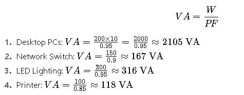
A small office has the following equipment:
| Equipment | Power (W) | Power Factor (PF) |
|---|---|---|
| Desktop PCs (10) | 200 W | 0.95 |
| Network Switch | 150 W | 0.9 |
| LED Lighting | 300 W | 0.95 |
| Printer | 100 W | 0.85 |
Objective:
Determine the total apparent power (VA) required to select an appropriate UPS.
Step 1: Calculate VA for each device

Step 2: Total Apparent Power
Step 3: Apply Safety Margin
A typical 25% safety margin ensures the UPS can handle startup surges and future expansions:
Step 4: Conclusion
A 3.5 kVA UPS is appropriate for this office. This ensures the system can handle peak loads and maintain stability.
Insights:
- Even though the total watts = 2000 + 150 + 300 + 100 = 2550 W, the UPS must handle 3383 VA due to the power factor effect.
- Choosing a UPS based solely on watts would have resulted in under-sizing.
Example 2: Industrial Motor Load
Scenario:
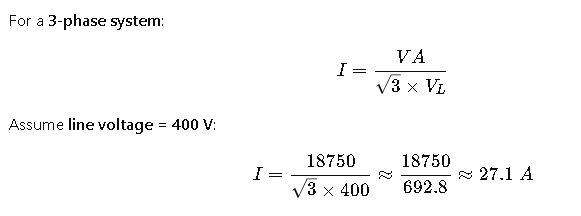
A factory uses a 3-phase induction motor rated at 15 kW, operating at 0.8 PF.
Objective:
Determine the line current and apparent power for proper transformer and cable sizing.
Step 1: Calculate Apparent Power (VA)
Step 2: Determine Line Current (3-Phase System)

Step 3: Consider Voltage Drop and Safety Factor
- Apply 10% extra for voltage drops and startup surges:
Step 4: Conclusion
- Apparent power required: 18.75 kVA
- Recommended circuit protection and cables: Rated for at least 30 A
Insights:
- Even though the motor consumes 15 kW, the electrical infrastructure must support ~18.75 kVA.
- Neglecting the power factor could result in overheating wires or tripping circuit breakers.
Practical Considerations for Engineers
- Power Factor Correction:
- Installing capacitors or PFC devices can raise PF closer to 1, reducing VA requirements and improving efficiency.
- Particularly important in industrial facilities with multiple inductive loads.
- UPS and Generator Sizing:
- Always calculate VA, not just W, to avoid undersizing.
- Include startup surges (motors, laser printers) and future expansion margin (usually 20–30%).
- Reactive Power (VAR) Management:
- Use VAR monitoring in SCADA or BMS systems to ensure that apparent power does not exceed transformer or cable ratings.
- Compliance with Standards:
- IEEE Std 141-1993, IEC 61000-3-2, and NEC guidelines dictate PF correction and equipment sizing.
- Proper sizing reduces energy losses, equipment wear, and improves grid stability.
Advanced Tips for Calculators and Software
1.Bidirectional Calculation:
- A modern Watts to VA calculator should support both directions:
2.Include adjustable PF input, as real-world devices rarely operate at PF = 1.
3.Dynamic Tables:
- Tables should cover 50 W–20 kW ranges with PF steps from 0.7 to 1.0.
- Provide instant lookup and automated rounding for commercial and industrial standards.
4.Integration with Load Analysis:
- Advanced calculators allow total load aggregation, handling multiple devices with varying PF and wattages.
- Include safety margins automatically based on application type.


