Understanding voltage (V), current (I), and resistance (R) relationships is essential in electrical engineering calculations. Ohm’s Law calculates any of these variables, enabling safe, efficient circuit design and analysis.
Volts → Resistance Calculator (Ohm’s Law)
Which formula is used?
Valid values
Common Voltage to Resistance Conversion Table
To facilitate quick calculations, here’s a table illustrating common voltage values and their corresponding resistance values for a constant current of 1 ampere:
| Voltage (V) | Resistance (Ω) |
|---|---|
| 1 V | 1 Ω |
| 5 V | 5 Ω |
| 10 V | 10 Ω |
| 12 V | 12 Ω |
| 24 V | 24 Ω |
| 48 V | 48 Ω |
| 110 V | 110 Ω |
| 220 V | 220 Ω |
| 240 V | 240 Ω |
| 1000 V | 1000 Ω |
Note: These values assume a current of 1 ampere for simplicity. Actual resistance will vary with different current levels.
Ohm’s Law Formulas and Variable Breakdown
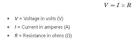
Ohm’s Law is expressed through three primary formulas:
1.Voltage (V):
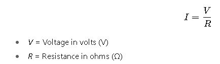
2.Current (I):
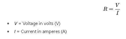
3.Resistance (R):
Detailed Explanation of Variables
- Voltage (V): The electrical potential difference between two points. It drives the flow of current through a conductor.
- Current (I): The rate of flow of electric charge, measured in amperes (A). It represents the quantity of electrons passing through a conductor per unit time.
- Resistance (R): The opposition to the flow of current, measured in ohms (Ω). It depends on the material, length, and cross-sectional area of the conductor.
Practical Examples of Voltage to Resistance Calculations
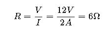
Example 1: Determining Resistance in a Simple Circuit
Scenario:
You have a circuit with a 12V battery and a current of 2A flowing through a resistor. To find the resistance:
Explanation:
Using Ohm’s Law, the resistance is calculated by dividing the voltage by the current. In this case, the resistor has a resistance of 6 ohms.
Example 2: Calculating Resistance for a Desired Current
Scenario:
You want to design a circuit where a 9V battery supplies a current of 0.5A. To achieve this, calculate the required resistance:
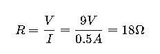
Explanation:
To ensure the desired current flows, the resistor must have a resistance of 18 ohms. This calculation is vital for selecting appropriate resistor values in circuit design.
Advanced Considerations in Voltage to Resistance Calculations
Temperature Effects on Resistance
The resistance of most materials changes with temperature. For conductors like copper, resistance increases with temperature. The temperature coefficient of resistance (α) quantifies this change:
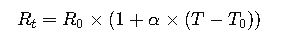
Where:
- R_t = Resistance at temperature T
- R_0 = Resistance at reference temperature T_0
- α = Temperature coefficient of resistance
- T = Temperature in degrees Celsius
- T_0 = Reference temperature in degrees Celsius
Non-Ohmic Materials
Not all materials obey Ohm’s Law. Non-ohmic materials have a resistance that varies with voltage and current. For instance, the filament of an incandescent bulb exhibits non-linear resistance; its resistance increases as it heats up due to increased temperature.
Extended Common Voltage to Resistance Values
For practical engineering applications, having a larger reference table helps select appropriate resistor values quickly. Assuming a standard current of 1 A:
| Voltage (V) | Resistance (Ω) | Voltage (V) | Resistance (Ω) |
|---|---|---|---|
| 1 V | 1 Ω | 50 V | 50 Ω |
| 2 V | 2 Ω | 60 V | 60 Ω |
| 3 V | 3 Ω | 70 V | 70 Ω |
| 4 V | 4 Ω | 80 V | 80 Ω |
| 5 V | 5 Ω | 90 V | 90 Ω |
| 6 V | 6 Ω | 100 V | 100 Ω |
| 7 V | 7 Ω | 120 V | 120 Ω |
| 8 V | 8 Ω | 150 V | 150 Ω |
| 9 V | 9 Ω | 200 V | 200 Ω |
| 10 V | 10 Ω | 300 V | 300 Ω |
| 12 V | 12 Ω | 500 V | 500 Ω |
| 15 V | 15 Ω | 1000 V | 1000 Ω |
| 20 V | 20 Ω | 2000 V | 2000 Ω |
| 24 V | 24 Ω | 5000 V | 5000 Ω |
| 30 V | 30 Ω | 10000 V | 10000 Ω |
Tip: For AC circuits or high-power applications, ensure to consider RMS values for voltage and current for accurate resistance calculations.
Best Practices in Voltage to Resistance Calculations
- Always Check Tolerance: Resistor manufacturing tolerances can affect the exact resistance. Common tolerances: ±1%, ±5%, ±10%.
- Account for Temperature: For high-precision circuits, calculate resistance change due to operating temperature.
- Use Appropriate Power Ratings: Prevent resistors from overheating by selecting correct wattage.
- Apply Safety Margins: Consider transient voltages and current spikes in design.
- Validate with Simulation Tools: Tools like LTSpice or PSpice can simulate circuit behavior before physical implementation.
External References for Authority
- IEEE Xplore Digital Library – Technical papers on resistive circuits
- All About Circuits – Ohm’s Law
- ScienceDirect – Electrical Engineering