Voltage drop calculations are essential for designing safe, efficient overhead electrical lines following IEC standards. IEC 60364-5-52 specifies maximum voltage drops between the installation origin and load points for proper equipment operation.
Voltage Drop Calculator – Overhead Lines (IEC)
Formulas used
Three-phase: Vd = √3·I·(R·L/1000 + X·L/1000)
Voltage Drop Calculation Formulae
1. Single-Phase Circuit (AC or DC)
For a single-phase circuit, the voltage drop (V) can be calculated using:
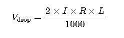
- I: Current in amperes (A)
- R: Resistance of the conductor in ohms per kilometer (Ω/km)
- L: Length of the conductor in kilometers (km)
2. Three-Phase Circuit
For a three-phase circuit, the voltage drop (V) is:
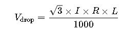
- I: Current in amperes (A)
- R: Resistance of the conductor in ohms per kilometer (Ω/km)
- L: Length of the conductor in kilometers (km)
These formulae are derived from Ohm’s Law, considering the resistive properties of the conductor. The factor of 2 in the single-phase formula accounts for the round trip of the current, while the factor of √3 in the three-phase formula adjusts for the phase difference.
Common Values and Parameters
Conductor Materials and Resistances
| Material | Resistivity (Ω·mm²/m) |
|---|---|
| Copper | 0.000000017 |
| Aluminum | 0.000000028 |
These values are essential for calculating the resistance per unit length of the conductor.
Standard Voltage Levels
| Voltage Level | Nominal Voltage (V) | Application |
|---|---|---|
| Low Voltage | 230/400 | Residential & Commercial |
| High Voltage | 1000 | Industrial & Transmission |
IEC 60038 specifies these standard voltages for electrical systems.
Practical Examples
Example 1: Single-Phase Residential Circuit
Given:
- Current (I) = 20 A
- Conductor Resistance (R) = 0.000000017 Ω·mm²/m
- Length (L) = 100 m
- Conductor Cross-Sectional Area (A) = 2.5 mm²
Calculation:
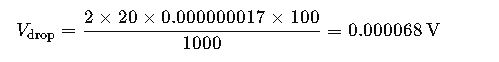
Analysis:
The calculated voltage drop is minimal, indicating efficient power delivery for the residential application.
Example 2: Three-Phase Industrial Circuit
Given:
- Current (I) = 50 A
- Conductor Resistance (R) = 0.000000017 Ω·mm²/m
- Length (L) = 200 m
- Conductor Cross-Sectional Area (A) = 10 mm²
Calculation:
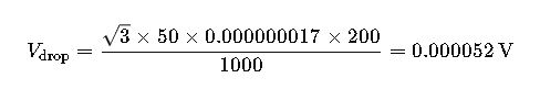
Analysis:
The voltage drop is within acceptable limits for industrial applications, ensuring the proper functioning of equipment.
Best Practices for Voltage Drop Management
- Conductor Selection: Choose materials with low resistivity, such as copper, to minimize voltage drop.
- Appropriate Sizing: Select conductor sizes that can handle the expected current without excessive voltage drop.
- Shorter Distances: Minimize the length of the conductor to reduce resistance and voltage drop.
- Regular Maintenance: Inspect and maintain overhead lines to ensure optimal performance and safety.
Understanding Voltage Drop in Overhead Lines
Voltage drop occurs when electrical energy is lost as current flows through a conductor due to its inherent resistance and reactance. In overhead lines, this phenomenon is influenced by:
- Conductor material: Copper and aluminum are the most common. Copper has lower resistivity, leading to smaller voltage drops. Aluminum is lighter and cheaper but results in higher drops for the same current.
- Line length: Longer lines naturally experience higher voltage drop. Designing for minimum distance between the power source and load reduces losses.
- Current magnitude: Higher currents increase voltage drop proportionally. Understanding peak and continuous current is essential.
- Conductor cross-section: Larger cross-sectional areas reduce resistance, thus reducing voltage drop.
IEC standards recommend maximum allowable voltage drops, typically 3–5% for low voltage systems and up to 7% for industrial installations, to ensure equipment operates efficiently.
Typical Parameters for Voltage Drop Calculators
When using a Voltage Drop Calculator for Overhead Lines, engineers must input several key parameters. Commonly used values include:
| Parameter | Typical Values | Notes |
|---|---|---|
| Conductor Material | Copper, Aluminum | Copper preferred for low drop; aluminum for cost-sensitive designs |
| Conductor Cross-section | 2.5 mm² – 400 mm² | Depends on current rating and line length |
| Line Voltage | 230/400 V, 11 kV, 33 kV | Low voltage (LV) for residential; medium/high voltage for industry |
| Line Length | 50 m – 10 km | Longer lines require larger conductors or multiple circuits |
| Load Current | 10 A – 500 A | Must consider peak and continuous loads |
| Power Factor | 0.8 – 1.0 | Lower power factors increase reactive losses and voltage drop |
These values allow a calculator to provide realistic and practical voltage drop predictions.
Practical Application Examples
Example 1: Residential Feeder Line
A residential neighborhood is fed from a transformer 500 m away. The line uses copper conductors of 16 mm², supplying multiple houses with a total load of 120 A.
Using standard voltage drop guidelines:
- Voltage drop is calculated per phase.
- The system is designed to remain below 3% drop, ensuring household appliances operate normally.
- The calculator helps engineers confirm conductor sizing or recommend using a larger cross-section if the drop exceeds limits.
Outcome: Proper sizing ensures lights and motors maintain performance without exceeding voltage drop standards.
Example 2: Industrial Plant Supply
An industrial plant requires a three-phase 11 kV supply over 2 km using aluminum conductors of 70 mm². Peak load is 250 A per phase, with a power factor of 0.9.
The voltage drop calculator allows:
- Determining whether conductors meet IEC standards for maximum 5% drop.
- Adjusting conductor size or adding parallel lines if voltage drop exceeds limits.
- Evaluating impact of load factor and operating hours on energy efficiency.
Outcome: Voltage drop remains within safe limits, preventing excessive energy losses and avoiding equipment malfunctions.
Key Considerations for Overhead Line Design
- Material Choice: Copper is preferred for high-performance lines; aluminum is suitable for budget-conscious installations.
- Line Routing: Minimizing line length reduces drop and energy losses.
- Load Balancing: Proper phase load distribution reduces excessive drops in one phase.
- Power Factor Correction: Using capacitors can reduce reactive losses and improve voltage stability.
- Environmental Factors: Temperature, wind, and weather conditions can slightly affect resistance and voltage drop over time.
- Periodic Verification: Using calculators periodically ensures that expansions or added loads do not exceed voltage drop limits.
Benefits of Using a Voltage Drop Calculator
- Accurate sizing of conductors and materials.
- Compliance with IEC standards, ensuring safety and reliability.
- Cost optimization, avoiding over-sizing or under-sizing conductors.
- Energy efficiency, reducing losses over long distances.
- Simplified planning for both residential and industrial overhead lines.