Voltage drop is critical in electrical engineering and power distribution systems. Current flowing through conductors encounters resistance.
This resistance reduces voltage between source and load. Excessive voltage drop harms equipment, wastes energy, and creates hazards.
Voltage Drop by Cable Distance & Cross-Section Calculator
What length should I enter?
Which formula is used?
1-phase AC: ΔV = 2 · I · (Rkm·cosφ + Xkm·sinφ) · Lkm.
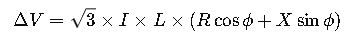
3-phase AC: ΔV = √3 · I · (Rkm·cosφ + Xkm·sinφ) · Lkm.
Rkm is temperature-adjusted resistance per kilometer derived from cross-section and material; Xkm is reactance per kilometer.
How is cable resistance obtained?
Then RT = R20 · [1 + α · (T − 20 °C)], with α≈0.00393 (Cu), 0.00403 (Al).
How accurate is reactance (X)?
How do I meet a target drop?
1. Understanding Voltage Drop and Why It Matters
When current flows through a conductor, resistive and reactive effects reduce the voltage available to the load.
Excessive voltage drop can cause:
- Reduced motor efficiency (motors run hotter, may fail prematurely).
- Dim lighting and unstable electronic equipment performance.
- Excessive heating in cables, increasing fire risk.
- Non-compliance with electrical codes such as the NEC (National Electrical Code) and IEC 60364.
Typical Maximum Voltage Drop Recommendations
| Standard / Application | Recommended Max Voltage Drop |
|---|---|
| NEC 210.19(A)(1) & 215.2(A)(3) Informational Note | 3% for branch circuits, 5% total feeder + branch |
| IEC 60364-5-52 | 3% for lighting, 5% for other uses |
| BS 7671 (UK Wiring Regulations) | 3% lighting, 5% other circuits |
| AS/NZS 3000 (Australia/New Zealand) | 5% general circuits |
2. Key Formulas for Voltage Drop Calculation
Voltage drop depends on the type of circuit (single-phase or three-phase), conductor material (copper or aluminum), operating frequency, and the cable’s resistive and reactive properties.
2.1 Single-Phase Voltage Drop Formula
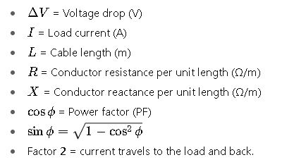
Where:
2.2 Three-Phase Voltage Drop Formula
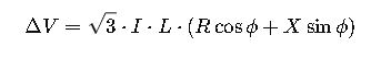
Where:
- Same variables as above, but factor changes from 2 to
 due to three-phase geometry.
2.3 Resistance and Reactance Values
The resistance R and reactance X depend on:
- Conductor material (Copper ~1.724 μΩ·cm, Aluminum ~2.826 μΩ·cm at 20°C)
- Temperature (resistance increases with temperature)
- Conductor cross-section (larger area = lower resistance)
- Cable construction (armored, multi-core, single-core)
Temperature Correction for Resistance:
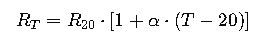
Where:
- RT= resistance at operating temperature (Ω/m)
- R20= resistance at 20°C (Ω/m)
- α= temperature coefficient (0.00393 for Cu, 0.00403 for Al)
- T= operating temperature (°C)
3. Common Resistance and Reactance Values
The following tables provide typical R and X values for Copper (Cu) and Aluminum (Al) conductors at 50 Hz, single-core, PVC-insulated, at 20°C.
3.1 Copper Conductor – R and X Values
| Cross-Section (mm²) | Resistance R (Ω/km) | Reactance X (Ω/km) |
|---|---|---|
| 1.5 | 12.10 | 0.080 |
| 2.5 | 7.41 | 0.078 |
| 4 | 4.61 | 0.076 |
| 6 | 3.08 | 0.075 |
| 10 | 1.83 | 0.073 |
| 16 | 1.15 | 0.072 |
| 25 | 0.727 | 0.070 |
| 35 | 0.524 | 0.069 |
| 50 | 0.387 | 0.067 |
| 70 | 0.268 | 0.066 |
| 95 | 0.193 | 0.065 |
| 120 | 0.153 | 0.064 |
| 150 | 0.124 | 0.064 |
| 185 | 0.0991 | 0.063 |
| 240 | 0.0754 | 0.062 |
3.2 Aluminum Conductor – R and X Values
| Cross-Section (mm²) | Resistance R (Ω/km) | Reactance X (Ω/km) |
|---|---|---|
| 10 | 3.08 | 0.073 |
| 16 | 1.91 | 0.072 |
| 25 | 1.20 | 0.070 |
| 35 | 0.868 | 0.069 |
| 50 | 0.641 | 0.067 |
| 70 | 0.443 | 0.066 |
| 95 | 0.320 | 0.065 |
| 120 | 0.253 | 0.064 |
| 150 | 0.206 | 0.064 |
| 185 | 0.164 | 0.063 |
| 240 | 0.125 | 0.062 |
Authoritative References:
- IEC 60364-5-52: Electrical installations of buildings – Selection and erection of wiring systems
- NFPA 70 – National Electrical Code (NEC)
- IEEE Std 141-1993 – Electrical Power Distribution
Frequently Asked Questions (FAQs) — Voltage Drop by Cable Distance and Cross-Section Calculator
1. What is voltage drop in electrical cables?
Voltage drop is the reduction in voltage as electrical current flows through a conductor due to its inherent resistance and reactance. It causes the voltage at the load end to be lower than the supply voltage, potentially impacting equipment performance.
2. Why is it important to calculate voltage drop in cable installations?
Calculating voltage drop ensures that electrical devices receive the proper voltage to operate efficiently and safely. Excessive voltage drop can lead to overheating, equipment malfunction, energy loss, and violation of electrical codes like NEC or IEC standards.
3. How does cable length affect voltage drop?
Voltage drop is directly proportional to the cable length. The longer the cable, the higher the resistance and reactance the current encounters, leading to greater voltage drop. That is why cable length must be a primary factor in cable sizing.
4. How do I calculate voltage drop for single-phase circuits?
Use the formula:
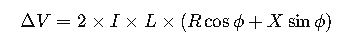
Where I is current, L is length, R resistance per meter, X reactance per meter, and cosϕ the power factor.
5. What is the difference in voltage drop calculation between single-phase and three-phase systems?
Single-phase systems use a factor of 2 (current goes to the load and back), whereas three-phase systems use ![]() due to their geometric relationship. The three-phase voltage drop formula is:
due to their geometric relationship. The three-phase voltage drop formula is:
6. Which conductor materials have lower voltage drop: copper or aluminum?
Copper has lower resistance compared to aluminum, so cables made with copper generally exhibit lower voltage drop for the same cross-sectional area and length.
7. What is an acceptable maximum voltage drop in electrical installations?
Most codes recommend a maximum voltage drop of 3% for lighting circuits and 5% for other circuits (total from supply to load). This helps maintain safe and efficient operation of equipment.
8. How does power factor influence voltage drop?
Voltage drop depends on the phase angle between current and voltage, represented by power factor. A lower power factor (more inductive load) increases the reactive component X sin ϕ, increasing voltage drop.
9. Can voltage drop be reduced by increasing cable size?
Yes. Increasing the conductor cross-sectional area reduces resistance RRR, which lowers voltage drop. However, larger cables are more expensive and harder to install, so the sizing must balance cost and performance.
10. Are there software tools or calculators to estimate voltage drop?
Yes, many online calculators and electrical design software (e.g., ETAP, SKM PowerTools) allow you to input parameters like current, length, conductor type, and get voltage drop instantly, following IEC or NEC formulas.
11. How do temperature and installation conditions affect voltage drop?
Higher conductor temperatures increase resistance, which raises voltage drop. Installation conditions such as conduit fill, ambient temperature, and cable grouping also affect cable resistance and reactance.