Accurate transformer sizing ensures electrical system safety, efficiency, and strict compliance with NEC and IEEE standards. This guide explains transformer sizing using load calculations, providing common values, formulas, examples, and applications.
Transformer Sizing Based on Load – NEC/IEEE
Formulas Used
Three-phase: I = Load / (√3·V·PF).
DC: I = Load / V.
NEC/IEEE Sizing Tips
Common Values for Transformer Sizing Based on Load Calculator – NEC, IEEE
The following table presents typical values used in transformer sizing calculations, including load types, power factors, and recommended transformer sizes based on NEC guidelines.
| Load Type | Voltage (V) | Current (A) | Power Factor (PF) | Calculated kVA | NEC Sizing Factor | Recommended Transformer kVA |
|---|---|---|---|---|---|---|
| Lighting Load | 120 | 50 | 1.0 | 6.0 | 1.25 | 7.5 kVA |
| Motor Load (Full Load) | 480 | 100 | 0.85 | 56.5 | 1.15 | 65 kVA |
| Receptacle Load | 208 | 75 | 0.95 | 16.4 | 1.25 | 20.5 kVA |
| HVAC Load | 240 | 120 | 0.9 | 32.0 | 1.15 | 37.0 kVA |
| Continuous Load | 600 | 200 | 0.85 | 141.0 | 1.25 | 175.0 kVA |
Note: These values are based on typical load conditions and may vary depending on specific application requirements.
Formulas for Transformer Sizing Based on Load Calculator – NEC, IEEE
Transformer sizing involves calculating the apparent power (kVA) required to meet the load demands. The following formulas are commonly used in transformer sizing calculations:
1. Single-Phase Transformer kVA Calculation
For single-phase systems:
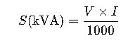
Where:
- S= Apparent power in kilovolt-amperes (kVA)
- V = Voltage (Volts)
- I= Current (Amperes)
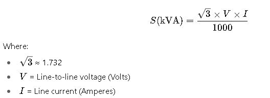
2. Three-Phase Transformer kVA Calculation
For three-phase systems:
3. Load Current Calculation from Power and Power Factor
To determine the load current based on power and power factor:
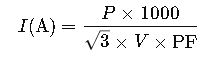
Where:
- P= Real power in kilowatts (kW)
- V = Line-to-line voltage (Volts)
- PF= Power factor (dimensionless)
4. Applying NEC Sizing Factors
NEC guidelines require transformers to be sized with safety margins to accommodate continuous loads and inrush currents. The sizing factor is applied as:

Where:
- Sizing Factor = 1.15 (115%) for non-continuous loads (NEC 450.3(A))
- Sizing Factor = 1.25 (125%) for continuous loads (NEC 450.3(B))
Note: The NEC sizing factors ensure that transformers can handle expected load variations and inrush currents without overloading.
Real-World Examples of Transformer Sizing Based on Load Calculator – NEC, IEEE
Example 1: Sizing a Transformer for a 3-Phase Motor Load
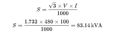
A facility requires a transformer to supply a 3-phase, 480V motor with a full load current of 100A and a power factor of 0.85. The motor operates continuously. Determine the minimum transformer kVA rating according to NEC guidelines.
Step 1: Calculate the apparent power (kVA) of the motor load
Step 2: Apply NEC sizing factor for continuous load (125%)

Step 3: Select the next standard transformer size
Standard transformer sizes are typically 75, 100, 112.5, 150 kVA, etc. The next size above 103.93 kVA is 112.5 kVA.
Recommended Transformer Size: 112.5 kVA
Example 2: Transformer Sizing for Mixed Lighting and Receptacle Loads
An office building has the following loads on a 208V, 3-phase system:
- Lighting load: 50 kW, power factor 1.0
- Receptacle load: 30 kW, power factor 0.95
- Continuous load factor: 100% for lighting, 80% for receptacles
Calculate the transformer size required according to NEC and IEEE standards.
Step 1: Calculate individual load kVA
Lighting kVA = 50 kW / 1.0 = 50 kVA
Receptacle kVA = 30 kW / 0.95 = 31.58 kVA
Step 2: Apply NEC demand factors
Assuming a demand factor of 0.75 for lighting and 0.80 for receptacles:
Lighting adjusted kVA = 50 kVA × 0.75 = 37.5 kVA
Receptacle adjusted kVA = 31.58 kVA × 0.80 = 25.26 kVA
Step 3: Calculate total adjusted load
Total adjusted load = 37.5 kVA + 25.26 kVA = 62.76 kVA
Step 4: Apply NEC sizing factor for continuous load (125%)
Step 5: Select the next standard transformer size
The next standard transformer size above 78.45 kVA is 100 kVA.
Recommended Transformer Size: 100 kVA
Additional Considerations for Transformer Sizing
When sizing transformers, several factors should be considered to ensure optimal performance and compliance with standards:
- Ambient Temperature: Higher ambient temperatures can reduce transformer efficiency and capacity. Adjustments may be necessary based on local climate conditions.
- Altitude: Operating at higher altitudes can affect transformer performance due to reduced cooling efficiency. De-rating factors should be applied accordingly.
- Load Characteristics: Understanding the nature of the load (e.g., constant, fluctuating, inductive) helps in selecting the appropriate transformer type and size.
- Future Expansion: Anticipating future load increases can guide in selecting a transformer with adequate capacity to accommodate growth.
Conclusion
Proper transformer sizing is crucial for the reliable and efficient operation of electrical systems. By adhering to NEC and IEEE guidelines, considering various factors, and applying appropriate formulas, engineers can ensure that transformers meet load demands without overloading or excessive costs. The provided examples and considerations serve as a foundation for making informed decisions in transformer selection and sizing.
For further reading and detailed standards, refer to the following resources:
- NEC Article 450 – Transformers
- IEEE Std C57.12.00 – General Requirements for Liquid-Immersed Distribution, Power, and Regulating Transformers
- IEEE Std C57.12.90 – Test Code for Liquid-Immersed Distribution, Power, and Regulating Transformers
By integrating these standards into the design and planning process, electrical engineers can enhance system reliability and safety.