Transformers are essential in power systems, and understanding losses ensures efficiency, reliability, and reduced operational costs.
This guide covers iron and copper losses based on IEC and IEEE standards, with examples.
Transformer Losses (Core & Copper) – IEC/IEEE
Advanced personalization (optional)
How do I use the reference presets?
How do copper losses scale?
How do core losses vary?
Where is maximum efficiency?
Formulas used
Voltage ratio: kV = V% / 100 and Pcore = Pcore,rated · kVn.
Temperature factor: kT = (Top+K)/(Tref+K) (°C).
Pcu,FL,adj = Pcu,FL · kT; Pcu(x) = Pcu,FL,adj · x².
Pout = (kVA · x · PF) kW; Ploss = Pcore + Pcu (W).
η = 100 · Pout / (Pout + Ploss/1000) (%).
Common Transformer Loss Values (IEC & IEEE)
The following table presents typical no-load (iron) and load (copper) losses for transformers, as per IEC and IEEE standards. These values are essential for assessing transformer efficiency and performance.
Transformer Losses Table
| Transformer Rating (kVA) | No-Load Loss (W) | Load Loss (W) |
|---|---|---|
| 50 | 100 | 200 |
| 100 | 150 | 300 |
| 200 | 250 | 500 |
| 500 | 400 | 800 |
| 1000 | 600 | 1200 |
| 2000 | 900 | 1800 |
| 5000 | 1500 | 3000 |
| 10000 | 2000 | 4000 |
Note: Values are approximate and can vary based on transformer design and manufacturer.
Formulas for Transformer Loss Calculations
1. No-Load Loss (Iron Loss)
No-load loss, also known as core loss, occurs due to the magnetization of the transformer core. It is relatively constant and independent of the load.
Formula:
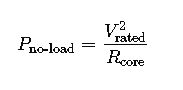
Where:
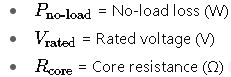
Note: Core resistance is determined based on the material and construction of the transformer core.
2. Load Loss (Copper Loss)
Load loss, or copper loss, arises due to the resistance of the windings when current flows through them. It increases with the square of the load current.
Formula:
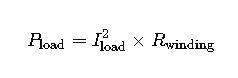
Where:
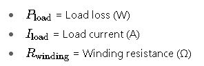
Note: Winding resistance is influenced by factors such as conductor material, temperature, and winding configuration.
Real-World Examples
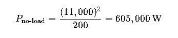
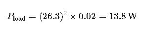
Example 1: 500 kVA Transformer
Given:
- Rated voltage: 11 kV
- Rated current: 26.3 A
- Core resistance: 200 Ω
- Winding resistance: 0.02 Ω
Calculations:
- No-Load Loss:
- Load Loss at Full Load:
Note: These values are simplified for illustrative purposes. Actual calculations may involve additional factors such as temperature corrections and stray losses.
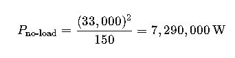
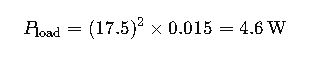
Example 2: 1000 kVA Transformer
Given:
- Rated voltage: 33 kV
- Rated current: 17.5 A
- Core resistance: 150 Ω
- Winding resistance: 0.015 Ω
Calculations:
- No-Load Loss:
- Load Loss at Full Load:
Note: These values are simplified for illustrative purposes. Actual calculations may involve additional factors such as temperature corrections and stray losses.
Additional Considerations
- Temperature Effects: Both core and winding resistances are temperature-dependent. Temperature corrections are essential for accurate loss calculations.
- Stray Losses: These are additional losses due to leakage fluxes and other non-ideal factors. They can be significant and should be considered in detailed analyses.
- Efficiency Optimization: Peak efficiency occurs when no-load losses equal load losses. Designing transformers to operate near this point can enhance overall performance.
Types of Transformer Losses
- Core Losses (Iron Losses / No-Load Losses)
- These losses occur in the transformer core due to the magnetization of the steel.
- They remain relatively constant regardless of the load and mainly depend on core material, frequency, and applied voltage.
- Reducing core losses is especially important for high-efficiency transformers that operate for long periods at low load.
- Copper Losses (Load Losses)
- These occur in the transformer windings due to the electrical resistance of copper (or aluminum).
- Copper losses increase with load and are often the dominant loss in transformers under high demand.
- Factors such as conductor cross-section, material type, operating temperature, and rated current directly affect these losses.
- Additional Losses
- These include losses from eddy currents in metallic parts, hysteresis in non-ferrous materials, and leakage flux.
- While smaller than core or copper losses, they can still impact overall efficiency, especially in large or specialized transformers.
Operational Impact of Losses
- Energy Efficiency:
Losses represent wasted energy converted into heat, increasing operational costs and cooling requirements. - Transformer Temperature:
Loss-generated heat raises the operating temperature, affecting insulation life and overall equipment reliability. - Transformer Selection and Design:
Understanding losses helps optimize design: choosing high-efficiency core materials, adjusting conductor sizing, and selecting transformers that minimize losses under typical operating loads.
Loss Optimization According to IEC and IEEE Standards
- High
-Quality Silicon Steel Core
- Using low-hysteresis, low-conductivity steel reduces core losses and eddy current losses.
- Winding and Conductor Design
- Increasing conductor cross-section or using high-conductivity copper reduces load (copper) losses.
- Energy-Efficient Transformers
- IEC and IEEE recommend loss-optimized transformers for critical or continuous-operation applications.
- Preventive Maintenance
- Regular inspections help detect increased losses due to loose connections, overheating, or insulation degradation.
Practical Applications
- Urban Power Distribution
Transformers supplying cities often operate many hours at low load; minimizing core losses is crucial for energy efficiency. - Industrial and Manufacturing Plants
In industrial settings, transformers often operate near full load. Copper losses dominate, and optimized winding designs reduce operating and maintenance costs. - Data Centers and Critical Electronics
High efficiency is crucial to minimize heat generation and energy consumption. Transformers are designed to reduce both core and copper losses, ensuring stability and reliability.
Benefits of Proper Loss Management
- Reduced Operating Costs – Less wasted energy translates into lower electricity bills.
- Extended Transformer Life – Lower heat improves insulation lifespan and component durability.
- Regulatory Compliance – Meeting IEC and IEEE standards ensures efficiency and reliability.
- Sustainability – Reduced energy consumption contributes to lower carbon emissions.