Transformer grounding is essential for electrical safety, protecting equipment, personnel, and ensuring NEC compliance effectively.
This guide explains NEC standards, sizing calculations, practical applications, and strategies for optimized transformer grounding.
Transformer Grounding Calculator (NEC)
What is transformer grounding?
How is grounding current calculated?
Grounding type selection
Common Values for Transformer Grounding According to NEC
Table 250.66 of the NEC provides guidelines for sizing grounding electrode conductors (GECs) based on the size of the largest ungrounded conductor. The table specifies minimum sizes for copper and aluminum conductors, considering various configurations and applications.
Table: NEC Table 250.66 – Grounding Electrode Conductor Sizes
| Largest Ungrounded Conductor Size (AWG or kcmil) | Copper GEC Size (AWG) | Aluminum GEC Size (AWG) |
|---|---|---|
| 6 AWG or smaller | 6 | 4 |
| 4 AWG | 4 | 2 |
| 2 AWG | 2 | 1 |
| 1 AWG | 1 | 1/0 |
| 1/0 AWG | 1/0 | 2/0 |
| 2/0 AWG | 2/0 | 3/0 |
| 3/0 AWG | 3/0 | 4/0 |
| 4/0 AWG | 4/0 | 250 kcmil |
| 250 kcmil | 250 kcmil | 350 kcmil |
| 350 kcmil | 350 kcmil | 500 kcmil |
| 500 kcmil | 500 kcmil | 750 kcmil |
| 750 kcmil | 750 kcmil | 1000 kcmil |
| 1000 kcmil | 1000 kcmil | 1250 kcmil |
Note: The sizes above are based on NEC Table 250.66 and are subject to change based on the latest NEC editions.
Formulas for Transformer Grounding Calculations
Proper grounding involves calculating the appropriate conductor sizes and ensuring compliance with NEC standards. Below are key formulas used in transformer grounding calculations:
1. Line Current Calculation
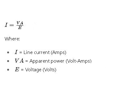
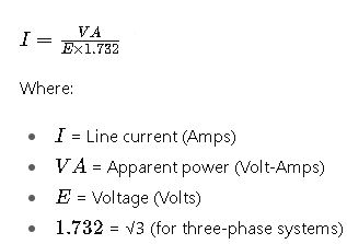
For a transformer, the line current can be calculated using the following formulas:
- Single-Phase System:

- Three-Phase System:

2. Grounding Electrode Conductor Size Calculation
The size of the GEC is determined based on the largest ungrounded conductor size, as specified in NEC Table 250.66. For instance, if the largest ungrounded conductor is 1/0 AWG copper, the minimum GEC size would be 1/0 AWG copper.
3. Overcurrent Protection Device (OCPD) Sizing
Overcurrent protection for transformers is calculated using NEC Table 450.3(B). The protection device size is typically 125% of the transformer full-load current.
Real-World Application Examples
Example 1: Sizing a GEC for a 45 kVA Transformer
Given:
- Transformer rating: 45 kVA
- Primary voltage: 480 V
- Secondary voltage: 208Y/120 V
- Largest ungrounded conductor: 1/0 AWG copper
Calculations:
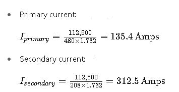
1.Primary current:
2. Secondary current:
2.Size the GEC: Referring to NEC Table 250.66, for a 1/0 AWG copper conductor, the minimum GEC size is 1/0 AWG copper.
3.Size the OCPD:
Using NEC Table 450.3(B), the OCPD size is 125% of the primary current:
The next standard size is 70 Amps.
Example 2: Sizing a GEC for a 112.5 kVA Transformer
Given:
- Transformer rating: 112.5 kVA
- Primary voltage: 480 V
- Secondary voltage: 208Y/120 V
- Largest ungrounded conductor: 2/0 AWG copper
Calculations:
1.Determine Full-Load Current:

2.Size the GEC: Referring to NEC Table 250.66, for a 2/0 AWG copper conductor, the minimum GEC size is 2/0 AWG copper.
3.Size the OCPD: Using NEC Table 450.3(B), the OCPD size is 125% of the primary current:
The next standard size is 175 Amps.
Additional Considerations
- Grounding Electrode Types: The type of grounding electrode (e.g., rod, plate, concrete-encased) influences the GEC sizing. For instance, NEC 250.66(A) allows for smaller GEC sizes when connecting to rod, pipe, or plate electrodes.
- Parallel Conductors: When using multiple parallel conductors, the total cross-sectional area is considered in GEC sizing. For example, two 500 kcmil copper conductors in parallel equate to a 1000 kcmil conductor for GEC sizing purposes.
- Overcurrent Protection Device (OCPD) Sizing: Proper OCPD sizing ensures protection against overcurrent conditions. NEC 450.3(B) provides guidelines for transformer OCPD sizing, typically at 125% of the transformer full-load current.
Conclusion
Transformer grounding is a vital component of electrical system design, ensuring safety and compliance with the NEC. By understanding and applying the appropriate formulas, tables, and considerations, electrical professionals can design effective grounding systems that protect both equipment and personnel.
For further learning, consider exploring the following resources:


