The calculation of full load current in three-phase motors is fundamental for reliable electrical engineering. It ensures proper sizing of conductors, protection devices, and compliance with IEC 60034 and IEC 60947.
Three-Phase Motor FLC Calculator (IEC)
Extended Table of Common Full Load Current Values (IEC-Based)
The following table presents typical full load currents for standard three-phase motors at 400 V, 50 Hz (the IEC standard supply condition). These values are approximate and may vary slightly depending on motor efficiency, power factor, and manufacturer specifications. However, they serve as reliable references for design and field applications.
Table 1. Approximate Three-Phase Motor Full Load Current (400 V, 50 Hz, IEC Standard)
| Motor Power (kW) | Motor Power (HP) | Efficiency (%) | Power Factor (cos φ) | Voltage (V) | Full Load Current (A) |
|---|---|---|---|---|---|
| 0.75 | 1 | 78 | 0.78 | 400 | 1.7 |
| 1.1 | 1.5 | 80 | 0.80 | 400 | 2.4 |
| 1.5 | 2 | 82 | 0.82 | 400 | 3.1 |
| 2.2 | 3 | 84 | 0.83 | 400 | 4.3 |
| 3 | 4 | 85 | 0.84 | 400 | 5.4 |
| 4 | 5.5 | 86 | 0.85 | 400 | 7.2 |
| 5.5 | 7.5 | 87 | 0.85 | 400 | 10.0 |
| 7.5 | 10 | 88 | 0.86 | 400 | 13.5 |
| 11 | 15 | 89 | 0.87 | 400 | 20.0 |
| 15 | 20 | 90 | 0.88 | 400 | 27.0 |
| 18.5 | 25 | 91 | 0.88 | 400 | 33.0 |
| 22 | 30 | 91 | 0.89 | 400 | 39.0 |
| 30 | 40 | 92 | 0.89 | 400 | 52.0 |
| 37 | 50 | 93 | 0.89 | 400 | 64.0 |
| 45 | 60 | 93 | 0.90 | 400 | 78.0 |
| 55 | 75 | 94 | 0.90 | 400 | 96.0 |
| 75 | 100 | 95 | 0.90 | 400 | 130.0 |
| 90 | 125 | 95 | 0.91 | 400 | 156.0 |
| 110 | 150 | 95 | 0.91 | 400 | 191.0 |
| 132 | 175 | 96 | 0.91 | 400 | 228.0 |
| 160 | 215 | 96 | 0.92 | 400 | 275.0 |
| 200 | 270 | 96 | 0.92 | 400 | 340.0 |
| 250 | 335 | 97 | 0.93 | 400 | 420.0 |
| 315 | 425 | 97 | 0.93 | 400 | 520.0 |
| 355 | 475 | 97 | 0.93 | 400 | 585.0 |
| 400 | 536 | 97 | 0.93 | 400 | 660.0 |
Notes on the table:
- Values are derived from IEC standards and manufacturer catalogs for squirrel-cage induction motors.
- Full load current increases as motor efficiency or power factor decreases.
- Voltage tolerance: ±10% as per IEC 60034.
Fundamental Formula for Three-Phase Motor Full Load Current (IEC-Based)
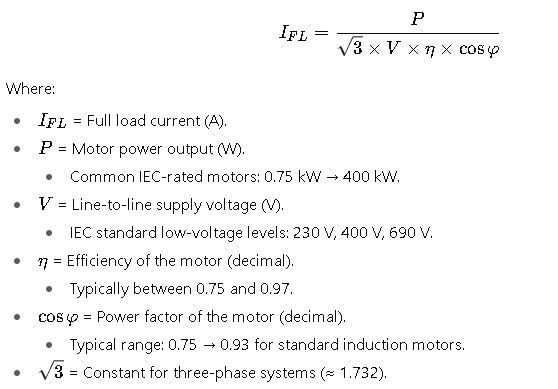
Step-by-Step Explanation of Each Variable
1. Motor Power (P)
- Defined as the mechanical output delivered at the motor shaft.
- Standard IEC rating units: kilowatts (kW).
- Conversion:

- Example: A 15 kW motor ≈ 20 HP.
2. Voltage (V)
- IEC recommends standard line-to-line voltages: 400 V (most common in Europe), 690 V for larger motors.
- Voltage deviations affect motor torque and current.
- Motors must comply with IEC 60034-1 voltage variation limits (±10%).
3. Efficiency (η)
- Ratio of mechanical power output to electrical power input.
- IEC IE efficiency classes:
- IE1 → Standard Efficiency
- IE2 → High Efficiency
- IE3 → Premium Efficiency
- IE4 → Super Premium Efficiency
4. Power Factor (cos φ)
- Indicates how effectively the motor converts electrical power into useful work.
- Typical IEC induction motor PF values: 0.78 to 0.93.
- Higher power factor = lower reactive current demand.
Real-World Applications of Three-Phase Motor Full Load Current Calculation
While theoretical values and formulas provide the foundation, engineers face challenges in real-world installations where load profiles, environmental conditions, and power quality influence the actual current drawn. Below are two detailed case studies that illustrate how the Three-Phase Motor Full Load Current Calculator (Based on IEC) is applied in practice.
Case Study 1: Sizing Conductors for a 55 kW Motor in an Industrial Plant
Scenario:
A cement plant requires a 55 kW, 400 V, 50 Hz, IE3 efficiency motor to drive a large conveyor belt. The design engineer must determine the full load current to size conductors, circuit breakers, and protection relays.
Step 1. Identify Parameters (from IEC catalog data):
- Motor Power: 55 kW
- Voltage: 400 V
- Efficiency (η): 0.94 (94%)
- Power Factor (cos φ): 0.89
Step 2. Full Load Current from Standard Table:
From Table 1 above, the typical current for a 55 kW IEC motor at 400 V ≈ 96 A.
Step 3. Engineering Decisions:
- Conductor Sizing: According to IEC 60364, copper conductors must handle 96 A continuously. For safety margin and ambient temperature derating, engineers select 4 × 25 mm² cables per phase.
- Circuit Breaker: A molded case circuit breaker (MCCB) rated at 125 A is chosen, with adjustable overload protection.
- Relay Coordination: A thermal overload relay is set to 1.05 × FLC ≈ 100 A.
Outcome:
The installation meets IEC 60364 requirements for safe operation, avoiding overheating and ensuring long-term reliability.
Key Insight:
Relying on standard IEC current tables simplifies design decisions and provides engineers with quick, reliable references without recalculating every time.
Case Study 2: Motor Starting Conditions in Water Treatment Facility
Scenario:
A water treatment plant operates a 90 kW, 400 V pump motor. During startup, engineers must evaluate the inrush current and ensure the power system can withstand the stress.
Step 1. Identify Parameters:
- Motor Power: 90 kW
- Voltage: 400 V
- Efficiency: 95%
- Power Factor: 0.91
Step 2. Full Load Current Reference:
From IEC tables, the FLC of a 90 kW motor ≈ 156 A.
Step 3. Starting Current Estimation:
- IEC and manufacturers typically estimate starting current = 6 × FLC for DOL (Direct-On-Line) starting.
- Starting Current = 6 × 156 A = 936 A.
Step 4. Engineering Considerations:
- Supply Transformer: Must handle inrush without excessive voltage dip. Transformer rating verified at 630 kVA.
- Starting Method: To reduce stress, a star-delta starter is implemented, limiting starting current to approx. 2 × FLC ≈ 310 A.
- Protection Settings: Protection relays configured for both overload and locked rotor conditions.
Outcome:
The correct selection of starting method and protective devices prevents nuisance tripping, voltage dips, and mechanical stress on pumps, while ensuring compliance with IEC 60947-4-1 (Contactors and motor starters).
Practical Insights from Field Applications
- Voltage Fluctuations: Motors operating below nominal voltage draw higher currents, accelerating insulation aging. IEC tolerances (±10%) must always be considered.
- Ambient Temperature: Higher temperatures reduce conductor ampacity. Engineers often oversize cables in hot industrial environments.
- Efficiency Class Impact: IE1 vs. IE4 motors can differ by 10–15% in current draw for the same power rating.
- Reactive Power Penalties: Low power factor leads to penalties in many countries. Correct sizing and use of capacitor banks are essential.
Advantages of Using IEC-Based Full Load Current Calculations
- Standardization: Ensures consistency across international projects.
- Safety Compliance: Meets electrical protection requirements of IEC 60364 and IEC 60947.
- Design Optimization: Avoids oversizing or undersizing cables, breakers, and starters.
- Predictive Maintenance: Knowing exact current values helps set thresholds for monitoring systems.