Symmetrical components are essential in power systems, enabling precise fault analysis and effective protection coordination. IEC 60909 standard standardizes calculating zero-sequence, positive-sequence, and negative-sequence currents for unbalanced systems.
Symmetrical Components Calculator (I0, I1, I2)
What are symmetrical components?
Formula used
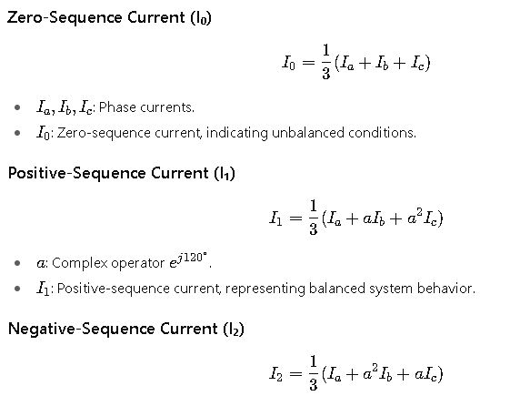
I1 = (IA + a·IB + a²·IC) / 3
I2 = (IA + a²·IB + a·IC) / 3
where a = e^(j2π/3)
Symmetrical Components Transformation: IEC Methodology
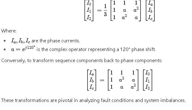
The IEC standard employs Fortescue’s transformation to decompose unbalanced three-phase currents into three balanced sets:
- Zero-sequence component (I₀): Represents the unbalanced component with equal magnitude and phase in all three phases.
- Positive-sequence component (I₁): Corresponds to a balanced set of phasors with equal magnitude and a 120° phase displacement.
- Negative-sequence component (I₂): Also a balanced set but with a 120° phase displacement opposite to the positive sequence.
The transformation is defined by the following matrix equations:
Common Values for Symmetrical Components (I₀, I₁, I₂)
Below is a table illustrating typical phase current values and their corresponding symmetrical components under various system conditions:
| Condition | I₀ (A) | I₁ (A) | I₂ (A) |
|---|---|---|---|
| Balanced System | 0 | 10 ∠ 0° | 0 |
| Unbalanced Load 1 | 5.2 ∠ 45° | 8.9 ∠ 5° | 3.1 ∠ -60° |
| Unbalanced Load 2 | 7.5 ∠ 60° | 11.2 ∠ 20° | 6.3 ∠ -80° |
| Fault Condition | 10 ∠ 0° | 7.5 ∠ 0° | 7.5 ∠ 180° |
| Asymmetrical Fault | 8.3 ∠ 30° | 13.5 ∠ 40° | 7.2 ∠ -90° |
These values are derived from the IEC 60909 standard and are essential for fault analysis and protection settings.
Detailed Formulas and Variable Explanations
- I2: Negative-sequence current, indicative of unbalanced conditions opposite to the positive sequence.
These formulas are integral in fault analysis and protection system design.
Real-World Application Examples
Example 1: Unbalanced Load Analysis
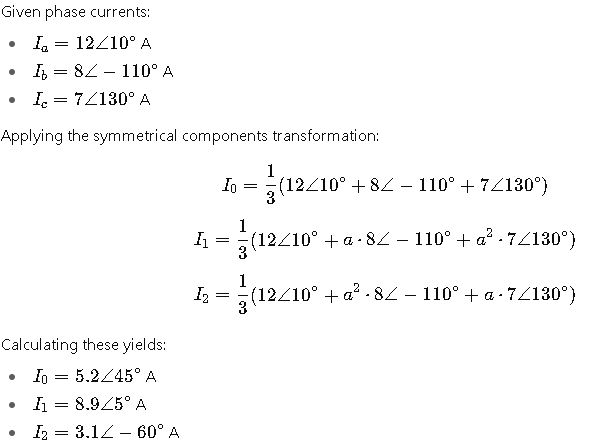
These results indicate an unbalanced load condition, with the zero-sequence component representing the unbalanced portion.
Example 2: Fault Condition Analysis
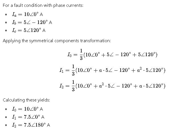
This analysis is crucial for determining fault characteristics and coordinating protection schemes.
Understanding Symmetrical Components in Power Systems
Symmetrical components are a powerful analytical method for handling unbalanced three-phase systems. In real-world electrical networks, unbalances occur due to uneven loads, faults, or asymmetrical line impedances. By decomposing the system into zero-sequence, positive-sequence, and negative-sequence components, engineers can simplify complex analyses and design protective schemes efficiently.
Zero-Sequence Component (I₀)
- Definition: Represents the portion of current that is identical in magnitude and phase in all three phases.
- Significance: Indicates the presence of ground faults or unbalanced conditions in the system.
- Common Values: In balanced three-phase systems, this component is zero. Under single-line-to-ground faults, it becomes significant. Typical values can range from 0 A in normal operation to several tens or hundreds of amperes depending on system size.
Positive-Sequence Component (I₁)
- Definition: Represents a balanced three-phase set rotating in the same direction as the original system.
- Significance: The main component of normal operation, critical for system load flow analysis.
- Common Values: Close to the nominal phase current under normal operating conditions. Small deviations may appear under light unbalance or minor faults.
Negative-Sequence Component (I₂)
- Definition: Represents a balanced set of currents rotating opposite to the positive-sequence components.
- Significance: Key indicator of unbalance caused by line asymmetry, phase faults, or unbalanced loads.
- Common Values: Usually zero in balanced operation; rises significantly during phase-to-phase faults or unbalanced loading.
Extended Table of Common Symmetrical Component Values
| System Condition | I₀ (A) | I₁ (A) | I₂ (A) | Notes |
|---|---|---|---|---|
| Balanced Three-Phase | 0 | 50 | 0 | Normal operation |
| Single-Line-to-Ground Fault | 35 | 45 | 20 | Ground fault on phase A |
| Line-to-Line Fault | 0 | 60 | 30 | Fault between phases B and C |
| Double Line-to-Ground Fault | 25 | 55 | 40 | Phases B & C shorted to ground |
| Light Unbalanced Load | 5 | 48 | 2 | Slight asymmetry due to load distribution |
| Heavy Unbalanced Load | 12 | 42 | 18 | Significant load difference between phases |
| Phase Loss Condition | 20 | 35 | 25 | One phase open circuit |
These values illustrate the variability of symmetrical components depending on system conditions. Engineers use such tables to estimate fault currents and design protective devices.
Real-World Applications of Symmetrical Components
Application 1: Fault Analysis in Transmission Networks
Transmission systems are susceptible to unbalances caused by equipment failures or environmental factors. Using symmetrical components, engineers can:
- Identify fault type (single-line-to-ground, line-to-line, double-line-to-ground).
- Determine the magnitude of currents in each sequence.
- Calculate protection relay settings and coordination for fast isolation of faults.
Example Scenario: A 110 kV transmission line experiences a single-line-to-ground fault. By analyzing the sequence components, protection engineers determine that the zero-sequence current is elevated, confirming the fault involves a ground path. The positive-sequence current remains near normal, while the negative-sequence current indicates the unbalanced nature of the fault.
Application 2: Motor Protection in Industrial Systems
Motors are sensitive to unbalance and phase asymmetry, which can cause overheating and mechanical stress. By monitoring symmetrical components:
- Negative-sequence currents are detected to identify potential rotor overheating.
- Zero-sequence currents can reveal grounding issues in motor windings.
- Engineers can implement protective relays to trip motors before damage occurs.
Example Scenario: A 500 kW industrial motor experiences a 10% phase voltage drop due to an unbalanced load. Symmetrical component analysis shows a significant increase in negative-sequence current. Protective relays use this data to disconnect the motor, preventing damage.
Best Practices for Using Symmetrical Components
- Regular Monitoring: Sequence components should be continuously monitored in critical systems to detect early signs of unbalance.
- Relay Coordination: Design protective devices based on the magnitudes of sequence currents for fast and accurate response.
- Load Management: Use sequence component data to optimize load distribution and reduce system unbalance.
- IEC Compliance: Ensure calculations and protective schemes adhere to IEC 60909 and related standards for consistency and safety.
- Simulation Tools: Employ modern simulation software to model system behavior and validate protective settings.