Understanding the relationship between kilowatts and volt-amperes is fundamental for electrical engineering, system design, and efficiency. Professionals across industries like data centers, manufacturing, and renewable energy require precise conversions for reliable equipment sizing.
kW ↔ kVA / VA Converter
Note: kW = kVA × PF. PF usually ranges between 0.8 and 1.0
| Unit | Relation |
|---|---|
| 1 kW | = 1.25 kVA (PF=0.8) |
| 1 kVA | = 0.8 kW (PF=0.8) |
| 1 kVA | = 1000 VA |
1. Understanding kW and VA
Before diving into calculations, it is crucial to understand what each unit represents:
- kW (kilowatt) → A measure of real power consumed by a load. It represents the actual work being performed, such as turning a motor or lighting a lamp.
- VA (volt-ampere) → A measure of apparent power, which includes both real power (kW) and reactive power (kVAR). Apparent power is the total power flowing in the circuit.
The link between the two is defined by the power factor (PF):
Where:
- VA = apparent power (volt-amperes)
- kW = real power (kilowatts)
- PF = power factor (a dimensionless number between 0 and 1)
2. Extensive Tables for Common Conversions
The following tables present common kW to VA conversions at different power factor (PF) levels. These are useful references for engineers when estimating equipment sizing.
Table 1: kW to VA Conversion at Power Factor = 1.0 (Ideal System)
| kW | VA |
|---|---|
| 0.5 | 500 |
| 1 | 1,000 |
| 2 | 2,000 |
| 5 | 5,000 |
| 10 | 10,000 |
| 20 | 20,000 |
| 50 | 50,000 |
| 100 | 100,000 |
| 200 | 200,000 |
| 500 | 500,000 |
| 1000 | 1,000,000 |
Table 2: kW to VA Conversion at Power Factor = 0.9 (Common in Industry)
| kW | VA |
|---|---|
| 0.5 | 556 |
| 1 | 1,111 |
| 2 | 2,222 |
| 5 | 5,556 |
| 10 | 11,111 |
| 20 | 22,222 |
| 50 | 55,556 |
| 100 | 111,111 |
| 200 | 222,222 |
| 500 | 555,556 |
| 1000 | 1,111,111 |
Table 3: kW to VA Conversion at Power Factor = 0.8 (Widely Used in Generators & UPS Sizing)
| kW | VA |
|---|---|
| 0.5 | 625 |
| 1 | 1,250 |
| 2 | 2,500 |
| 5 | 6,250 |
| 10 | 12,500 |
| 20 | 25,000 |
| 50 | 62,500 |
| 100 | 125,000 |
| 200 | 250,000 |
| 500 | 625,000 |
| 1000 | 1,250,000 |
Table 4: kW to VA Conversion at Power Factor = 0.7 (Low Efficiency Loads)
| kW | VA |
|---|---|
| 0.5 | 714 |
| 1 | 1,429 |
| 2 | 2,857 |
| 5 | 7,143 |
| 10 | 14,286 |
| 20 | 28,571 |
| 50 | 71,429 |
| 100 | 142,857 |
| 200 | 285,714 |
| 500 | 714,286 |
| 1000 | 1,428,571 |
3. Key Formulas Explained
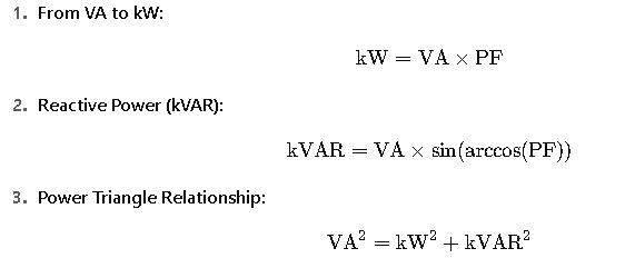
The core relationship is:
But in practice, other related formulas are equally important:

Explanation of Variables
- kW (Real Power):
Represents the portion of power that actually performs useful work. Common in motor ratings, resistive heaters, and lighting systems. - VA (Apparent Power):
Represents the product of voltage and current in the circuit. Used for equipment sizing, since conductors and transformers must carry this total power. - Power Factor (PF):
A ratio between real power and apparent power. It is influenced by load type:- Purely resistive loads → PF = 1.0
- Mixed loads with inductive components (motors, compressors) → PF = 0.7 – 0.9
- Poorly corrected industrial systems → PF < 0.7
- kVAR (Reactive Power):
The non-working component of power, caused by inductance or capacitance. Though it does not perform real work, it increases current and losses in the system.
4. Real-World Applications of kW to VA Conversion
Understanding the kW to VA relationship is not just theoretical — it has direct implications in industries ranging from data centers and hospitals to manufacturing plants and renewable energy systems. Below are two detailed case studies showing how professionals apply kW to VA conversions in practice.
Case Study 1: Sizing a UPS System for a Data Center
Scenario:
A data center needs an Uninterruptible Power Supply (UPS) to back up critical servers. The IT team has calculated that the total real power consumption of the servers and networking equipment is 200 kW.
Step 1: Identify Power Factor
- Most IT equipment operates with a power factor close to 0.9 (modern servers use active power factor correction).
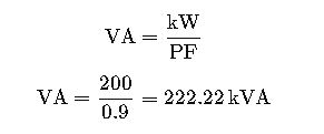
Step 2: Apply Formula
Step 3: Add Safety Margin
- Industry standards recommend oversizing by 20% to accommodate future expansion.
Step 4: Select UPS System
- The engineering team selects a 270 kVA UPS system, ensuring reliable performance even under load growth.
Takeaway: The kW to VA calculator ensures proper UPS sizing, avoiding undersized systems (risking shutdowns) or oversized systems (increasing costs unnecessarily).
Case Study 2: Industrial Motor Load with Low Power Factor
Scenario:
A factory operates several induction motors totaling 150 kW of real power. Due to the inductive nature of motors, the average power factor is 0.75.
Step 1: Convert kW to VA
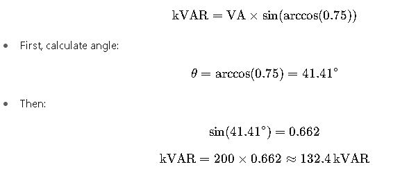
Step 2: Calculate Reactive Power (kVAR)

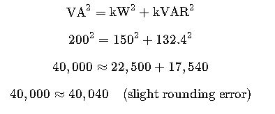
Step 3: Power Triangle Check
Verified.
Step 4: Consider Power Factor Correction
- To improve efficiency, capacitors could be installed to raise PF closer to 0.95, reducing apparent power demand:
Result:
By correcting PF, the system reduces from 200 kVA → 158 kVA, which means lower demand charges and reduced stress on transformers and cables.
5. Why Power Factor Matters in kW to VA Conversions
The power factor plays a critical role in real-world applications:
- PF = 1.0 (Unity) → 100% efficient transfer of energy. Rare in practice.
- PF = 0.9 → Typical for IT loads and modern electronics.
- PF = 0.8 → Common for industrial generators and UPS specifications.
- PF < 0.7 → Found in older equipment or heavily inductive loads; costly for utilities.
Consequences of Low Power Factor:
- Oversized equipment required (cables, transformers, generators).
- Higher energy losses due to excessive current.
- Utility penalties in many countries (e.g., IEC and IEEE standards require minimum PF compliance).
- IEEE 1459-2010 Standard on Power Definitions provides an authoritative reference on how active, reactive, and apparent power should be measured and interpreted.
6. Extended Formula Applications
Beyond the simple kW ↔ VA conversion, professionals often need to calculate related electrical parameters:
- Current Calculation in Single-Phase Systems
Where:
- I= current (amperes)
- V= voltage (volts)
- Current Calculation in Three-Phase Systems
Where:
- VLL= line-to-line voltage
- Real Power from Current & Voltage
These formulas link power, voltage, and current, enabling complete design of distribution systems, UPS setups, and generator capacity planning.
7. Practical Tips for Engineers
- Always check manufacturer datasheets for actual PF values — assumed PF can lead to incorrect sizing.
- In critical facilities (hospitals, data centers), always include a 20–25% safety margin when converting kW to VA.
- Regularly monitor PF with power quality analyzers to avoid unexpected demand charges.
- For renewable energy systems (solar + battery storage), account for inverter PF, which often ranges from 0.85 to 0.95.


