Feeder Cable Sizing AWG for transformer Calculator : Best Must-Have NEC Tool
Feeder cable sizing requires precise calculations, NEC compliance, and attention to voltage drop and efficiency.
This article supplies calculators, AWG tables, formulae, examples, and best NEC tool practices for engineers.
Feeder Cable Sizing (AWG) for Transformer — NEC-oriented Technical Tool
Regulatory context and primary requirements for feeder conductor sizing
Electric feeders to transformers and from transformers must satisfy multiple NEC constraints simultaneously:
- Ampacity: conductor ampacity must be equal to or greater than the calculated continuous and non‑continuous currents (NEC tables and articles).
- Overcurrent protection coordination: the conductor ampacity must be compatible with OCPD sizing rules.
- Voltage drop: recommended maximum feeder voltage drop typically 3% to the furthest load; combined feeder and branch circuit commonly limited to 5%.
- Temperature and adjustment factors: insulation rating, ambient temperature, and grouping require correction factors applied to table ampacities.
- Short‑circuit and coordination: available fault current and protective device ratings must be considered.The National Electrical Code (NEC) (NFPA 70) provides the primary U.S. normative baseline. For international projects, align NEC principles with IEC 60364, manufacturer instructions, and IEEE/NEMA guidance for conductor properties and transformer application.
Key formulas used by an NEC‑aware transformer feeder calculator
Below are the essential formulas that any professional feeder calculator must implement. Each formula is provided with variable explanations and typical values.Formula: single‑phase full‑load current (transformer secondary or primary)
I = (kVA × 1000) / V
- I = current in amperes (A)
- kVA = transformer rated kilovolt‑amperes (typical values: 15 kVA, 75 kVA, 150 kVA)
- V = line voltage (for single‑phase, line to line; typical: 120/240 V, 240 V)
Example typical: 75 kVA at 240 V → I = (75 × 1000) / 240 = 312.5 AFormula: three‑phase full‑load current
I = (kVA × 1000) / (√3 × V)
- √3 ≈ 1.732
- V = line‑to‑line voltage (typical values: 480 V, 415 V, 400 V)
Example typical: 150 kVA at 480 V → I = (150 × 1000) / (1.732 × 480) ≈ 180.4 AFormula: continuous load conductor correction
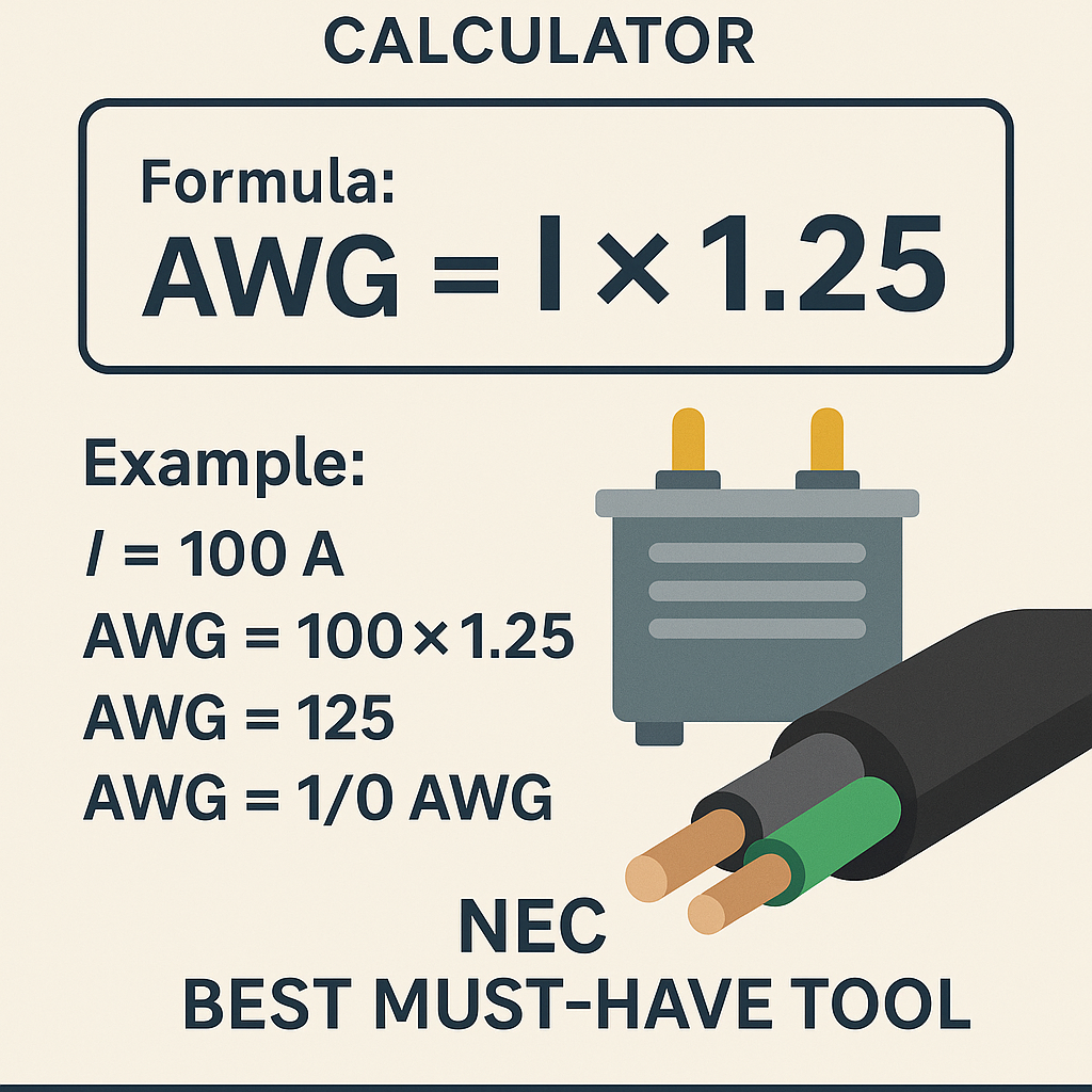
Ireq = I × 1.25
- Ireq = required conductor ampacity for continuous loads (NEC requires 125% for continuous loads)
- Use when the load is continuous (expected to run 3 hours or more)Formula: voltage drop (single‑phase)
Vdrop = I × R × L × 2
- Vdrop = voltage drop in volts
- I = current (A)
- R = conductor resistance in ohms per foot (use tabulated ohms/1000 ft divided by 1000)
- L = one‑way length in feet (distance from source to load)
- Factor 2 accounts for round trip (out and back)Formula: voltage drop (three‑phase)
Vdrop = I × R × L × 1.732
- multiplier 1.732 (√3) for three‑phase circuits when using line‑to‑line voltages and symmetrical conductorsFormula: percent voltage drop
%Vdrop = (Vdrop / V) × 100
- Use V = system nominal voltage (line voltage for three‑phase)Formula: conductor resistance conversion
R (Ω/ft) = R (Ω/1000 ft) / 1000
- Typical R values depend on conductor material, size, and temperatureAll calculators must allow selection of insulation temperature rating (60°C, 75°C, 90°C) to pick appropriate ampacity table values and then apply ambient/derating corrections.
NEC ampacity reference (common AWG sizes) — typical values
AWG / kcmil
Copper Ampacity (75°C typical)
Copper Ampacity (90°C typical)
Aluminum Ampacity (75°C typical)
14
20 A
25 A
—
12
25 A
30 A
—
10
35 A
40 A
—
8
50 A
55 A
40 A
6
65 A
75 A
50 A
4
85 A
95 A
65 A
3
100 A
115 A
75 A
2
115 A
130 A
90 A
1
130 A
150 A
110 A
1/0
150 A
170 A
125 A
2/0
175 A
195 A
145 A
3/0
200 A
225 A
170 A
4/0
230 A
260 A
195 A
250 kcmil
255 A
285 A
215 A
350 kcmil
310 A
335 A
260 A
500 kcmil
380 A
420 A
320 A
600 kcmil
420 A
475 A
360 A
Notes:
- These are representative ampacities commonly used in feeder design references and NEC tables; always verify with the edition of the NEC and insulation type used.
- Choose the conductor ampacity from the column matching the ampacity temperature rating allowed by the equipment terminal rating (NEC 110.14(C)).
Typical conductor resistance and reactance values (useful for voltage drop)
AWG / kcmil
R (Ω/1000 ft) copper (20°C typical)
Approx. X (Ω/1000 ft) copper
4/0
0.0490
0.046
3/0
0.0620
0.050
2/0
0.0780
0.055
1/0
0.0983
0.060
1
0.1239
0.065
2
0.1563
0.070
3
0.1970
0.080
4
0.2485
0.090
6
0.3951
0.105
8
0.6282
0.125
10
0.9990
0.150
Notes:
- R values listed are typical DC resistances at 20°C. R increases with temperature; many voltage drop calculations use DC R adjusted for conductor operating temperature or use standardized R values at 75°C.
- X (reactance) depends on conductor spacing and installation method; calculator must allow adding X or use a typical combined impedance factor.
Transformer currents and common feeder recommendations
Transformer rating
Voltage
Full‑Load Current
Suggested minimum copper feeder (no derate)
15 kVA
240 V single‑phase
62.5 A
8 AWG (50 A) → if continuous use 6 AWG (65 A)
45 kVA
240 V single‑phase
187.5 A
3/0 copper (200 A) typically
75 kVA
240 V single‑phase
312.5 A
500–600 kcmil copper depending on continuous load and conditions
75 kVA
480 V three‑phase
90.1 A
3 AWG copper (100 A) typically
150 kVA
480 V three‑phase
180.4 A
4/0 copper (230 A) recommended if continuous load
500 kVA
480 V three‑phase
601.0 A
600–700 kcmil copper in parallel or single large conductors per NEC rules
Comments:
- These suggested feeder sizes are starting points. Correct sizing must apply continuous load correction, ambient/derating, and voltage drop. Always reconcile with actual ampacity tables and equipment terminal ratings.
Accounting for continuous loads and ambient temperature correction
Design steps that a compliant feeder calculator must perform:
1. Determine actual transformer full‑load current using the kVA and system voltage formulas.
2. Determine whether the downstream load is continuous (NEC defines continuous as 3 hours or more). If continuous, multiply the calculated current by 1.25 before selecting conductor ampacity.
3. Select conductor ampacity based on the conductor insulation temperature rating and terminal temperature rating. Use the appropriate ampacity table column (e.g., 75°C or 90°C).
4. Apply correction factors for ambient temperature and for more than three current‑carrying conductors in a raceway/cable per NEC 310.15(B)(1) and Table 310.15(B)(2)(a) (or the edition-specific table).
5. Size for voltage drop: calculate voltage drop and, if above allowed limits (commonly 3% feeder), increase conductor size or accept higher drop with documented justification.
6. Consider harmonics and neutral sizing for single‑phase loads on multi‑wire systems; use IEEE/NEC guidance.
Ambient correction example
- If a copper conductor rated at 75°C has base ampacity 230 A (4/0) and the ambient temperature is 40°C with insulation rating factor of 0.91 (example value), the corrected ampacity becomes 230 × 0.91 = 209.3 A.
- If the feeder serves a continuous load producing required ampacity of 225 A, 4/0 at this ambient is inadequate; next conductor up should be selected.
Paralleling conductors and NEC constraints
NEC has strict rules on paralleling conductors:
- Only conductors of size 1/0 AWG copper or larger (and the equivalent aluminum sizes) are generally permitted to be paralleled, and only where specifically allowed by NEC section on conductor paralleling.
- Parallel conductors must be the same conductor material, size, length, and termination type, and must be installed in the same raceway or duct bank to ensure balanced impedance.
- A compliant calculator must:
- Warn if calculated conductor size exceeds feasible single‑conductor sizes and propose paralleling per NEC rules.
- Enforce that only permitted sizes are paralleled, and compute how many parallel conductors are required (rounded up to an integer).
Best‑must‑have features in an NEC‑aware feeder/transformer calculator tool
A professional tool should include:
- System type selection: single‑phase or three‑phase, system voltage, high leg details.
- Transformer data entry: kVA, primary and secondary voltages, winding configuration, %Z (impedance) for short‑circuit calculations.
- Load profile entry: continuous vs non‑continuous, load factor, diversity, power factor, harmonic content.
- Conductor selection: material (copper/aluminum), insulation type (THHN, XHHW‑2), conduit/cable arrangement, temperature rating.
- Ampacity table engine for multiple NEC editions and the ability to choose the terminal temperature rating (per NEC 110.14).
- Automatic ambient temperature and conductor grouping correction factors and neutral sizing options.
- Voltage drop calculator including R and X per conductor size and ability to include X or use a combined impedance.
- Paralleling logic enforcing NEC constraints and producing recommended equal length parallel runs.
- Report generation that documents all code sections applied, assumptions, and links to referenced normative documents.
- Fault current calculation for short‑circuit rating checks using transformer impedance and utility/source contributions.
Example 1 — Detailed single‑phase transformer feed (complete calculation)
Project: A 75 kVA single‑phase transformer, 240 V secondary, feeding a continuous industrial load located 150 ft from the transformer secondary terminals. Copper conductors, THHN, conductor temperature rating 75°C. The load is continuous (operates > 3 hours). Target maximum feeder voltage drop 3%.Step 1 — Calculate full‑load current:
I = (kVA × 1000) / V = (75 × 1000) / 240 = 312.5 AStep 2 — Apply continuous load multiplier:
Ireq = 312.5 × 1.25 = 390.625 AStep 3 — Select conductor ampacity (from ampacity table):
- From the ampacity table above, 500 kcmil copper at 75°C ≈ 380 A — insufficient (380 < 390.625).
- 600 kcmil copper at 75°C ≈ 420 A — adequate (420 ≥ 390.625).
Therefore select 600 kcmil copper as minimum conductor size for ampacity.Step 4 — Voltage drop check:
- Use typical resistance R for 600 kcmil copper (approx. 0.0308 Ω/1000 ft; convert to per foot: 0.0000308 Ω/ft). (Calculator should allow exact R from manufacturer table.)
- One‑way length L = 150 ft → round trip = 300 ft.
- Vdrop = I × R × L × 2 (single‑phase) = 390.625 × 0.0000308 × 150 × 2
(Or simplified: Vdrop = I × (R per ft) × 2 × L)
Compute:
- R per ft = 0.0000308
- Vdrop = 390.625 × 0.0000308 × 300 ≈ 3.61 V
%Vdrop = (3.61 / 240) × 100 ≈ 1.5%Result:
- 600 kcmil copper provides required ampacity and yields a voltage drop ≈ 1.5%, below the 3% target.
- Verify termination temperature ratings and equipment terminal limitations; if equipment terminals are limited to 75°C, the selection is consistent. If equipment is 60°C, conductor ampacity must be selected from the 60°C column or adjusted accordingly.Documentation and notes:
- If ambient temperature or multiple conductors in the raceway reduce ampacity, upsizing may be necessary.
- Confirm conductor bundling or conduit fill that may trigger further correction factors.
Example 2 — Detailed three‑phase transformer feed (complete calculation)
Project: A 150 kVA three‑phase distribution transformer with a 480 V secondary. Feeder length 200 ft (one‑way). Loads include motors with potential continuous duty estimated as 80% of transformer rating (not strictly continuous per NEC but heavy loading). Copper conductors, XHHW‑2, 90°C rating permitted at terminations, but equipment terminals rated at 75°C.Step 1 — Full‑load current:
I = (kVA × 1000) / (√3 × V) = (150 × 1000) / (1.732 × 480) ≈ 180.4 AStep 2 — Consider continuous load rule conservatively:
If feeder must serve loads that are effectively continuous, apply 125%:
Ireq = 180.4 × 1.25 ≈ 225.5 AStep 3 — Choose conductor ampacity column consistent with equipment terminal rating:
- Equipment terminals rated 75°C → select ampacity from 75°C column.
- From table: 4/0 copper at 75°C ≈ 230 A → adequate (230 ≥ 225.5).
Thus select 4/0 copper.Step 4 — Voltage drop evaluation (three‑phase):
- Use typical R for 4/0 copper ≈ 0.0490 Ω/1000 ft → R per ft = 0.0000490 Ω/ft.
- Vdrop = I × R × L × √3 = 225.5 × 0.0000490 × 200 × 1.732
Compute:
- Intermediate: R × L = 0.0000490 × 200 = 0.0098 Ω
- I × (R × L) = 225.5 × 0.0098 ≈ 2.21 V
- Multiply by √3: Vdrop ≈ 2.21 × 1.732 ≈ 3.83 V
%Vdrop = (3.83 / 480) × 100 ≈ 0.80%Result:
- 4/0 copper meets ampacity and yields a percent voltage drop well within 3% feeder allowance.
- If paralleling were considered, calculate required conductor quantity while respecting NEC paralleling rules (1/0 or larger and equal lengths).
Short‑circuit considerations and transformer inrush/current ordering
- Transformer inrush currents may be 5 to 10 times rated current for a few cycles on energization. This transient is short in duration and normally not limiting for conductor ampacity, but the overcurrent protective device and selective coordination must anticipate inrush.
- For feeder conductor thermal withstand and protective device coordination, calculate maximum available fault current using transformer %Z and source details. The conductor short‑circuit rating (or fuse/breaker interrupting rating) must be adequate.
- Use transformer impedance (%Z) and source contributions to compute prospective fault current per standard methods; a professional calculator must compute fault currents and check conductor and device ratings.
Harmonics, neutral sizing, and special cases
- Nonlinear loads (VFDs, rectifiers) produce harmonic currents that can increase neutral conductor current (especially 3rd harmonics). For transformers feeding nonlinear loads, the neutral or grounding conductor may need upsizing to handle harmonic sums; consult IEEE 519 and NEC guidance.
- Three‑phase four‑wire systems with significant single‑phase nonlinear loads may require special harmonic mitigation or oversized neutrals.
- For high inrush or motor loads, consider K‑factor transformers or inrush limiting devices.
International considerations
- Outside the U.S., IEC 60364 and local standards govern conductor sizing and selection. Key international differences:
- Ampacity tables and temperature ratings may differ.
- Voltage levels and harmonics profiles vary by region.
- Always cross‑reference local regulations and manufacturer installation instructions.
- For global projects, a calculator must permit selection of code basis (NEC, IEC) and display differences in assumptions and adjustment factors.
Practical checklist for feeder sizing using an NEC tool
Use this checklist during design:
1. Define system: single‑phase or three‑phase, nominal voltages.
2. Enter transformer kVA and winding configuration.
3. Specify load types and continuous load percentages.
4. Choose conductor material and insulation type.
5. Confirm equipment terminal temperature rating (60°C/75°C/90°C).
6. Apply continuous multiplier where required (1.25).
7. Apply ambient temperature and bundling derating factors.
8. Calculate voltage drop and compare with allowable limits.
9. Check paralleling rules if conductor > allowable single size.
10. Compute short‑circuit currents and verify conductor and OCPD withstand/interrupting ratings.
11. Document all referenced NEC sections and assumptions.
References, standards, and authoritative resources
Below are authoritative resources to consult when designing feeders and transformer connections:
- NFPA: National Electrical Code (NEC), NFPA 70 — https://www.nfpa.org/nec
- NEC ampacity and cable ampacity tables — consult the edition of NEC adopted by the authority having jurisdiction.
- IEEE Standards — transformer and grounding guidance — https://standards.ieee.org
- IEC 60364 — electrical installations of buildings (international reference) — https://www.iec.ch
- NEMA — transformer application guides and conductor data — https://www.nema.org
- Copper Development Association (conductor resistivity and data) — https://www.copper.org
- Manufacturer application guides and datasheets (e.g., Eaton, Siemens, Schneider Electric) — consult equipment-specific installation documents for terminal temperature ratings and torque values.
Final recommendations for engineers and tool implementers
- Always document assumptions and the specific NEC edition used for calculations. Code editions change, and ampacity values/correction tables are edition‑dependent.
- Ensure the tool reports step‑by‑step calculations: raw currents, derating steps, voltage drop math, and final conductor recommendation with alternatives.
- Incorporate safety margins, but avoid oversizing without reason; oversizing increases cost and may present other issues (mechanical, conduit fill).
- For international projects, allow toggling between NEC and IEC workflows and provide conversion notes.
- Maintain links to normative references and manufacturer documentation within the calculation report for permit submittals and AHJ review.This article provides the technical foundation and examples required to implement an NEC‑aware feeder cable sizing calculator for transformer applications, showing the interplay between ampacity, continuous load rules, voltage drop, and practical installation constraints.Feeder Cable Sizing Awg For Transformer Calculator Nec Best Must Have Nec Tool Guide