In electrical engineering, understanding transformer equivalent resistance and reactance is essential for design and analysis.
These parameters determine transformer performance, efficiency, and behavior under varying operating conditions and standards compliance.
Transformer Equivalent Resistance & Reactance (IEC / IEEE)
What voltages do I use?
How do I get R and X from %Z and X/R?
How do I use %Z and load loss?
Standards note (IEC / IEEE)
Transformer Equivalent Resistance and Reactance: A Detailed Overview
Transformers, as vital components in electrical power systems, exhibit inherent resistive and reactive characteristics due to their windings and magnetic core. These characteristics influence voltage regulation, efficiency, and fault analysis.
Equivalent Resistance (Re)
The equivalent resistance of a transformer reflects the combined effect of the resistances of both primary and secondary windings, referred to a common side (primary or secondary). It accounts for the real power losses due to the resistance of the windings.
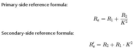
- Formula:
Re = R1 + (R2 / K²)- Re: Equivalent resistance referred to the primary side.
- R1: Resistance of the primary winding.
- R2: Resistance of the secondary winding.
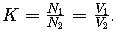
- K: Turns ratio (N1/N2).
Alternatively, for resistance referred to the secondary side:
- Formula:
Re’ = R2 + (R1 × K²)- Re’: Equivalent resistance referred to the secondary side.
Equivalent Reactance (Xe)
The equivalent reactance represents the combined effect of the leakage reactances of both windings, referred to a common side. It influences the transformer’s impedance and short-circuit behavior.
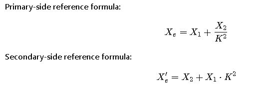
- Formula:
Xe = X1 + (X2 / K²)- Xe: Equivalent reactance referred to the primary side.
- X1: Leakage reactance of the primary winding.
- X2: Leakage reactance of the secondary winding.
For reactance referred to the secondary side:
- Formula:
Xe’ = X2 + (X1 × K²)- Xe’: Equivalent reactance referred to the secondary side.
Impedance (Z)
Impedance is the vector sum of resistance and reactance, influencing the transformer’s voltage drop and short-circuit current.
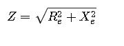
- Formula:
Z = √(Re² + Xe²)- Z: Impedance.
- Re: Equivalent resistance.
- Xe: Equivalent reactance.
Common Values for Equivalent Resistance and Reactance
The following table presents typical values for equivalent resistance and reactance in transformers, based on industry standards and practices.
| Transformer Rating (kVA) | Voltage Level (kV) | Referred to Primary Side (Ω) | Referred to Secondary Side (Ω) | Xe Referred to Primary Side (Ω) | Xe Referred to Secondary Side (Ω) |
|---|---|---|---|---|---|
| 25 | 11 / 0.415 | 0.015 | 0.00015 | 0.05 | 0.0005 |
| 100 | 11 / 0.415 | 0.06 | 0.0006 | 0.2 | 0.002 |
| 200 | 11 / 0.415 | 0.12 | 0.0012 | 0.4 | 0.004 |
| 500 | 11 / 0.415 | 0.3 | 0.003 | 1.0 | 0.01 |
| 1000 | 11 / 0.415 | 0.6 | 0.006 | 2.0 | 0.02 |
Note: Values are approximate and can vary based on transformer design and manufacturer specifications.
Real-World Applications and Examples
Example 1: Short-Circuit Analysis
In a power distribution network, a 100 kVA transformer with a primary voltage of 11 kV and a secondary voltage of 0.415 kV is subjected to a short-circuit fault. The transformer has the following parameters:
- R1 = 0.06 Ω
- R2 = 0.0006 Ω
- X1 = 0.2 Ω
- X2 = 0.002 Ω
- K = 11 / 0.415 ≈ 26.5
Calculate the equivalent resistance and reactance referred to the primary side:
- Re = R1 + (R2 / K²) = 0.06 + (0.0006 / 26.5²) ≈ 0.0601 Ω
- Xe = X1 + (X2 / K²) = 0.2 + (0.002 / 26.5²) ≈ 0.200003 Ω
The impedance is:
- Z = √(Re² + Xe²) ≈ √(0.0601² + 0.200003²) ≈ 0.208 Ω
This impedance value is crucial for determining the fault current and assessing the transformer’s performance during fault conditions.
Example 2: Voltage Regulation Calculation
For the same transformer, under full-load conditions, the voltage regulation can be estimated using the equivalent impedance. Assuming a rated current of 5.8 A on the primary side:
- Voltage drop (V_drop) = I × Z = 5.8 A × 0.208 Ω ≈ 1.2064 V
- Voltage regulation (%) = (V_drop / Rated Voltage) × 100 = (1.2064 V / 11,000 V) × 100 ≈ 0.01096%
This low voltage regulation indicates efficient transformer performance with minimal voltage drop under load.
Extended Tables of Common Equivalent Resistance and Reactance Values
For engineers working with transformers, having reference tables of typical values speeds up design, analysis, and troubleshooting. Below is an expanded table showing a wider range of transformer ratings, voltage levels, and corresponding equivalent resistance and reactance values based on IEC and IEEE recommendations.
| Transformer Rating (kVA) | Voltage Level (kV) | Referred to Primary Side (Ω) | Referred to Secondary Side (Ω) | Xe Referred to Primary Side (Ω) | Xe Referred to Secondary Side (Ω) |
|---|---|---|---|---|---|
| 25 | 11 / 0.415 | 0.015 | 0.00015 | 0.05 | 0.0005 |
| 50 | 11 / 0.415 | 0.03 | 0.0003 | 0.1 | 0.001 |
| 100 | 11 / 0.415 | 0.06 | 0.0006 | 0.2 | 0.002 |
| 200 | 11 / 0.415 | 0.12 | 0.0012 | 0.4 | 0.004 |
| 250 | 33 / 0.415 | 0.18 | 0.0015 | 0.6 | 0.005 |
| 500 | 11 / 0.415 | 0.3 | 0.003 | 1.0 | 0.01 |
| 750 | 33 / 0.415 | 0.45 | 0.0045 | 1.5 | 0.015 |
| 1000 | 11 / 0.415 | 0.6 | 0.006 | 2.0 | 0.02 |
| 1500 | 33 / 0.415 | 0.9 | 0.009 | 3.0 | 0.03 |
| 2000 | 66 / 11 | 1.2 | 0.012 | 4.0 | 0.04 |
These values are representative and can vary based on design, core material, cooling method, and manufacturer.
Detailed Formulas and Variable Explanations
1. Equivalent Resistance (Re)
The equivalent resistance is the sum of the resistances of the primary and secondary windings, referred to the same side.
- R1: Primary winding resistance (Ω), typically measured at 75°C per IEC 60076-1.
- R2: Secondary winding resistance (Ω).
- K: Turns ratio
Typical R1 and R2 values depend on transformer rating and material; smaller transformers have higher resistances due to smaller conductors.
2. Equivalent Reactance (Xe)
The equivalent reactance accounts for leakage flux and winding geometry.
- X1: Primary leakage reactance (Ω) — caused by non-ideal coupling between windings.
- X2: Secondary leakage reactance (Ω).
- K: Transformer turns ratio.
Leakage reactance values usually range from 2% to 6% of transformer base impedance for distribution transformers.
3. Transformer Impedance (Z)
The combined effect of Re and Xe forms the transformer impedance:
- Z: Total impedance (Ω).
- Re: Equivalent resistance (Ω).
- Xe: Equivalent reactance (Ω).
This impedance directly affects short-circuit currents and voltage regulation.
4. Short-Circuit Current Calculation
Short-circuit currents are crucial for protective device selection:
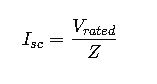
Where:
- V_rated: Transformer nominal voltage.
- Z: Total equivalent impedance.
5. Voltage Regulation
Voltage regulation quantifies voltage drop under load:
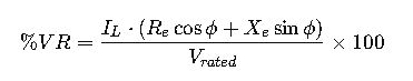
- I_L: Load current.
- ϕ: Load power factor angle.
Lower VR indicates better voltage stability and efficiency.
Real-World Case Studies
Case Study 1: Industrial Transformer Short-Circuit Analysis
- Transformer rating: 500 kVA, 11 kV / 0.415 kV
- R1 = 0.3 Ω, R2 = 0.003 Ω, X1 = 1 Ω, X2 = 0.01 Ω
- Turns ratio K = 26.5
Calculations:
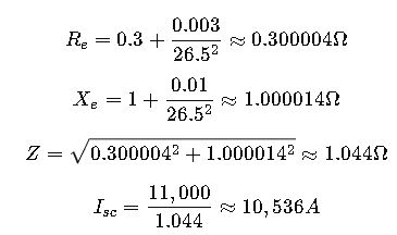
Engineers use this current to size protection devices and evaluate mechanical stresses during faults.
Case Study 2: Distribution Transformer Voltage Regulation
- Transformer rating: 250 kVA, 33 kV / 0.415 kV
- Re = 0.18 Ω, Xe = 0.6 Ω
- Load current: 6 A, power factor 0.8 lagging

Very low VR indicates stable voltage delivery for sensitive industrial equipment.