This article analyzes duct bank layout calculations, constraints, and grouping for multiple conduits efficiently safely.
Engineers require precise spacing, fill, thermal, and structural checks to ensure code compliance system reliability.Electrical Duct Bank Layout Calculator – Multiple Conduits with Spacing and Row Grouping Constraints
Scope and technical objectives for duct bank arrangement
This document provides a systematic, calculation-driven method to arrange multiple conduits in duct banks while respecting spacing, grouping, and thermal constraints. It targets electrical engineers and designers responsible for underground power distribution substations, campus utilities, and industrial plant feeders.
Key objectives include: optimize conduit center-to-center spacing, determine grouping-related ampacity derating, check conduit fill and soil thermal effects, evaluate mechanical cover and concrete encasement, and provide worked examples for real design cases.
Regulatory and normative framework
Design of duct banks must reference applicable codes and standards that govern raceway fill, ampacity derating, grounding, and installation practices. Primary international and regional references include:
- NFPA 70 (NEC) — National Electrical Code: ampacity adjustment and conduit fill rules. Refer: https://www.nfpa.org/ (search NFPA 70 / NEC)
- IEEE standards relevant to soil thermal properties and power cable ampacity: IEEE Std 442 (soil thermal resistivity), IEEE Std 399 (power system analysis guidelines): https://standards.ieee.org/
- IEC 60364 series — electrical installations of buildings for international practice: https://www.iec.ch/
- NEMA and manufacturer guides for conduit and duct products (e.g., NEMA FB 1): https://www.nema.org/
- Local utility standards and civil engineering codes for trenching, cover, and concrete encasement.
Fundamental variables and definitions
Before presenting formulas, define primary variables used in duct bank layout and thermal analysis:
- D = Conduit outside diameter (OD).
- Di = Conduit internal diameter (ID) or internal available area for cable fill.
- s = Center-to-center spacing between adjacent conduits.
- e = Edge-to-edge spacing = s - D.
- Nc = Number of conduits in the duct bank.
- Ncc = Number of current-carrying conductors or cables that influence mutual heating (per grouping).
- I_load = Required circuit current (A).
- I_tab = Tabulated ampacity for a conductor or cable at reference conditions (A).
- F_adj = Adjustment factor for grouping (from NEC or relevant regulation, decimal).
- F_temp = Correction factor for ambient/soil temperature deviation (decimal).
- k = Soil thermal conductivity (W/m·K) — typical range provided below.
- R_th = Thermal resistance between conductor and ambient per unit length (°C/W·m or °C per W per metre).
Core formulas (HTML notation only) and variable explanations
1) Adjustment for grouping (basic ampacity requirement):
Required ampacity after grouping adjustment:
Variables:
- I_required — ampacity a conductor must have before additional temperature corrections (A).
- I_load — continuous design current (A).
- F_adj — grouping adjustment factor (decimal; e.g., 0.8 for 4–6 conductors).
Typical F_adj values from NEC Table 310.15(B)(3)(a):
| Number of Conductors (Ncc) | Adjustment Factor F_adj |
|---|---|
| 1–3 | 1.00 |
| 4–6 | 0.80 |
| 7–9 | 0.70 |
| 10–20 | 0.50 |
| 21–30 | 0.45 |
| 31–40 | 0.40 |
| >40 | 0.35 |
2) Combined correction for grouping and ambient/soil temperature:
Variables:
- F_temp — temperature correction factor from conductor ampacity tables (e.g., 0.91 for 40°C rating vs 30°C base).
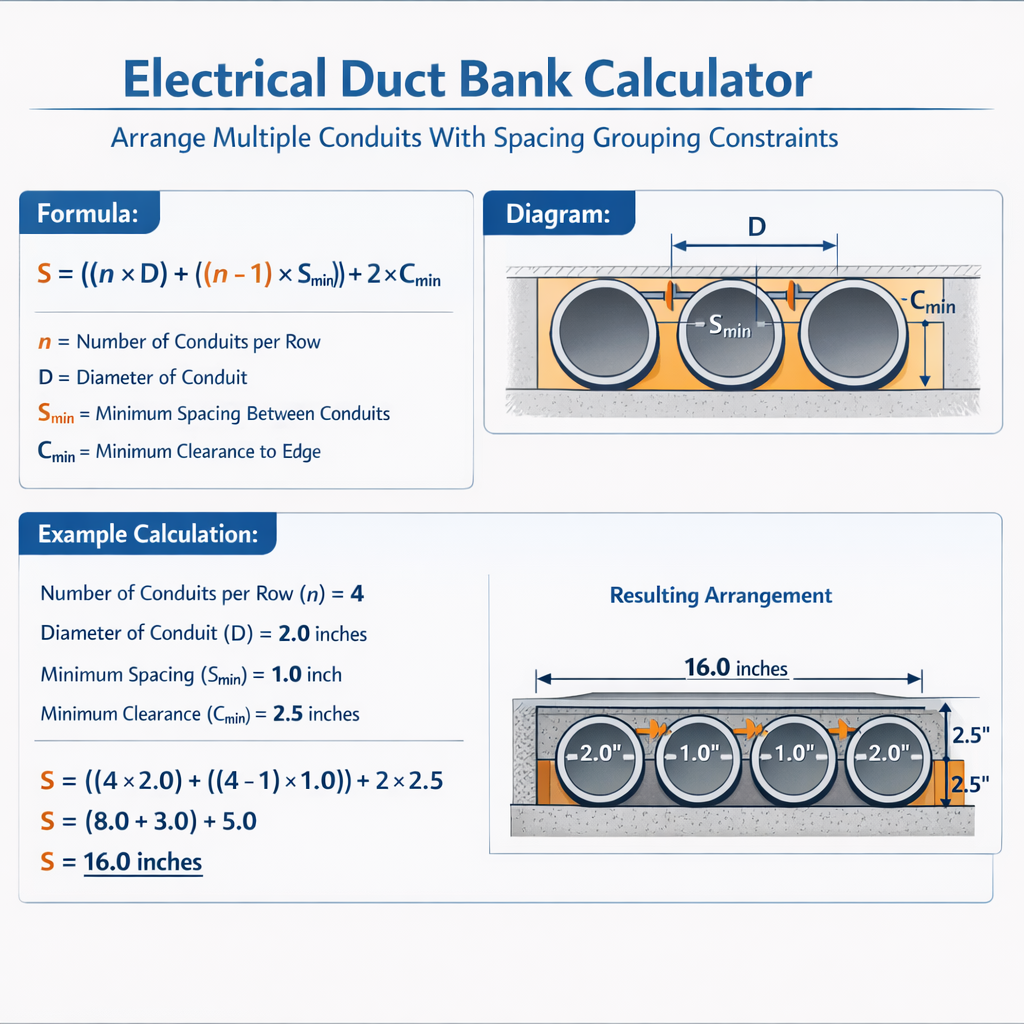
3) Center-to-center spacing and edge clearance calculations:
Where:
- s — center-to-center spacing (mm or in).
- D — conduit OD (same units).
- e — desired edge-to-edge separation between adjacent conduit surfaces.
Design heuristics often express spacing as a multiple of D. For example:
- Compact pack: s = 1.0 × D (touching: e = 0).
- Minimum thermal spacing recommended: s = 1.2 × D (e = 0.2D).
- Reduced derating target spacing: s ≥ 1.5 × D up to 2.0 × D.
4) Thermal resistance (simplified series model):
Where:
- R_cond — thermal resistance of conductor and insulation to conduit wall (°C/W·m).
- R_conduit — resistance through conduit material and filling (°C/W·m).
- R_soil — thermal resistance of surrounding soil per unit length (°C/W·m), often approximated from soil thermal conductivity k.
Typical soil thermal conductivity values (k) and implications:
| Soil Condition | Thermal Conductivity k (W/m·K) |
|---|---|
| Dry loose sand | 0.2 – 0.4 |
| Moist sand / silt | 0.5 – 1.0 |
| Clay (moist) | 0.8 – 1.5 |
| Crushed rock / concrete backfill | 1.0 – 2.5 |
Rough conversion (for simple screening):
R_soil ≈ 1 / (2π × k) × ln(r_outer / r_conduit)
Variables:
- r_conduit — effective radius of heat source (m).
- r_outer — effective radius to undisturbed soil temperature (m); depends on trench geometry.
- Note: More accurate estimation requires finite-element or standards-based thermal analysis (IEEE Std 442).
Conduit fill and mechanical constraints
Conduit fill rules control how many conductors or cables can be placed inside a conduit. Guidance:
- Follow manufacturer's cable dimensions and conduit internal cross-sectional area (Di and area).
- Single cable: typically permitted up to 53% area fill for a single conductor, subject to local rules and cable type.
- Multiple conductors: area fill limits typically 40% for two or more conductors in a conduit (verify with applicable table in local code and manufacturer datasheets).
- Keep minimum bending radius per cable design to avoid conductor damage; enforce pull tension limits.
| Common EMT Trade Size | Approx. OD (in) | Approx. ID (in) | Internal Area (in²) |
|---|---|---|---|
| 1/2" | 0.706 | 0.622 | 0.304 |
| 3/4" | 0.922 | 0.824 | 0.533 |
| 1" | 1.163 | 1.049 | 0.865 |
| 1-1/4" | 1.540 | 1.360 | 1.453 |
| 2" | 2.375 | 2.067 | 3.360 |
Note: Values shown are representative and vary by conduit schedule and manufacturer. Always confirm with product datasheets.
Optimization strategies for spacing and grouping
When arranging multiple conduits, follow a stepwise optimization process:
- Determine Nc and expected Ncc (count of current-carrying conductors that contribute to heating).
- Select conduit trade size(s) based on cable diameter and fill limits.
- Choose an initial packing geometry: single row, two-row (staggered), three-row, or racetrack. Common layouts: inline rectangular, staggered hexagonal close pack (improved thermal performance if adequate spacing).
- Estimate F_adj from Ncc; compute I_required. Compare with tabulated conductor ampacity; if insufficient, increase conduit size, reduce grouping (split circuits across banks), or increase spacing to reduce heat coupling.
- Adjust trench geometry, backfill material (higher thermal conductivity), or add concrete encasement to reduce R_th and allow higher ampacity.
Practical geometric layouts and comparison
Two common layouts:
- Linear: conduits placed in a single row; minimal footprint but high mutual heating when conduits are adjacent.
- Rectangular staggered (e.g., 2×3): balances footprint and thermal separation; choose vertical separation between rows if possible.
| Layout | Typical center spacing (s/D) | Thermal interaction (qualitative) |
|---|---|---|
| Single row touching | 1.0 | High |
| Staggered 2-row | 1.2 – 1.5 | Moderate |
| Square 2×2 with spacing | 1.5 – 2.0 | Lower |
| Wide spacing or separate banks | >2.0 | Minimal |
Example 1 — Medium-voltage feeder ducts (detailed)
Problem statement:
Design a duct bank for six identical single-core power cables feeding three parallel feeders (two circuits). Each cable current rating (tabulated) is 400 A at 90°C insulation and tabulated for a reference ambient/soil condition. All six cables are installed in six separate conduits within one duct bank array (Nc = 6 conduits). Continuous design current per conductor is 380 A. Soil thermal conductivity is moderate (k = 0.9 W/m·K). Target: determine whether grouping adjustment reduces allowable ampacity below the required 380 A and propose remedial measures if necessary.
Step 1 — Count current-carrying conductors:
Ncc = 6 (each conduit contains one current-carrying conductor influencing mutual heating).
Step 2 — Select adjustment factor F_adj from normative table:
For Ncc = 4–6, F_adj = 0.80.
Step 3 — Compute required ampacity before temperature correction:
Substitute:
Interpretation:
- If the tabulated ampacity I_tab for the chosen conductor at reference conditions is ≥ 475 A, the design passes grouping requirement.
- Typical conductor selection: consider conductor whose tabulated rating at 30°C ambient is 500 A (for 90°C insulation rated cables). If I_tab = 500 A then proceed to temperature correction:
Result:
- Tabulated conductor of 500 A meets I_required_corrected exactly; margin is minimal.
- If vendor tabulated ampacity is lower (e.g., 460 A), mitigation is required: increase conduit spacing, use higher-rated conductor, reduce cables per bank, or improve thermal backfill (higher k) or add concrete encasement.
Mitigation options evaluated:
- Increase spacing so that thermal interaction is reduced; effectively this can allow treating Ncc as fewer effective conductors for derating. E.g., spacing that reduces effective coupling may justify F_adj = 1.0 (if thermal separation eliminates interactive heating per utility guidelines).
- Switch to conductor with higher ampacity (e.g., larger cross-section or different insulation type rated for higher temperature).
- Use concrete encasement/backfill with k ≈ 1.5 W/m·K to reduce R_soil; often allows higher tabulated ampacity per manufacturer tables.
Example 2 — Low-voltage distribution with dense packing (complete)
Problem statement:
Facility requires routing twelve 3-phase circuits using single-conductor cables. Each circuit uses three conductors (phase only; neutrals separate). Minimum continuous current per conductor is 200 A. Design must employ available duct bank space with Nc = 12 conduits arranged as 3 rows of 4 conduits each within a trench. Determine grouping adjustment, required conductor ampacity, and recommend spacing/mitigation.
Step 1 — Count current-carrying conductors affecting mutual heating:
Assume each conduit contains one current-carrying conductor per phase; because all conductors belong to active circuits, consider that all 12 conductors are in proximity and contribute to mutual heating. Thus Ncc = 12.
Step 2 — Select F_adj for Ncc = 10–20: F_adj = 0.50.
Step 3 — Compute required ampacity:
Interpretation:
- A conductor with tabulated ampacity I_tab >= 400 A at reference conditions is required. If standard chosen cable's I_tab = 350 A, the grouping causes non-compliance.
Step 4 — Evaluate mitigation alternatives:
- Split the 12 conduits into two banks of 6 conduits each separated by a minimum clear distance to reduce mutual heating between banks. For two banks of 6 (each with Ncc = 6), F_adj per bank = 0.80. New required ampacity per conductor would be 200 / 0.80 = 250 A, which permits smaller conductor sizes.
- Increase spacing between conduits within the bank and between banks so that mutual heating reduces (consult manufacturer or perform thermal simulation). If spacing and backfill justify treating groups as ≤3 effectively then F_adj could be 1.0.
- Apply higher-conductivity backfill (cement-bentonite slurry) or concrete encasement per manufacturer to increase allowable I_tab per cable in soil.
Step 5 — Structural/checks:
- Verify trench depth, concrete cover and mechanical shielding consistent with local code for mechanical protection and load-bearing (vehicle traffic), with typical cover > 600 mm for vehicular load depending on authority.
- Ensure conduit materials and diameter accommodate pulling lengths, fish tapes, and scheduled bending radius for selected cable diameters.
Thermal simulation and practical modeling notes
For critical projects (large feeders, high ambient soil temperature, restricted spacing), use one or more of the following:
- Manufacturer ampacity calculation software, which incorporates cable geometry, trench geometry, and soil k.
- Finite-element thermal modeling to compute R_th and steady-state conductor temperature for given loading profile.
- Field measurement and soil resistivity testing in accordance with IEEE Std 442 to obtain accurate k values for design.
Installation practices and civil integration
Implementation must coordinate civil and electrical disciplines. Consider:
- Trench width sufficient to place ducts with required spacing and pour concrete where required.
- Use of warning tapes, tracer wire, and access points for future cable pulls and maintenance.
- Containment and jointing details to ensure watertight runs in flood-prone areas.
- Document as-built duct bank coordinates, depth to top of bank, conduit run lengths, and joint IDs for later maintenance and load studies.
Quality assurance and verification testing
After installation but before energization:
- Verify conduit depths, spacing and cover via survey.
- Perform continuity tests for tracer wires and perform cable megger and sheath tests per commissioning plan.
- Confirm backfill material and compaction meet specified thermal properties and civil requirements.
Reference tables and values for rapid engineering assessment
The following tables give rapid reference items used in early-stage engineering; verify final selection against manufacturer data sheets and applicable sections of NEC and local codes.
| Conduit OD (mm) | Conduit ID (mm) | Area (mm²) | Typical Max # of 4/0 copper cables (approx) |
|---|---|---|---|
| 21 (3/4") | 20 | 314 | 1 |
| 27 (1") | 26 | 531 | 1 |
| 34 (1-1/4") | 33 | 855 | 2 (tight) |
| 48 (2") | 46 | 1662 | 3 |
| 63 (2-1/2") | 61 | 2925 | 4 |
| Soil/Backfill Type | Typical k (W/m·K) | Effect on Ampacity |
|---|---|---|
| Native dry sand | 0.2–0.4 | Reduces allowable ampacity; consider improved backfill |
| Moist sand/silt | 0.5–1.0 | Typical default for many sites |
| Cement-bentonite slurry backfill | 1.0–1.6 | Improves ampacity significantly |
| Concrete encasement | 1.0–2.5 | Best practical solution for high ampacity or tight spacing |
Best practices and checklist for project delivery
- Confirm Ncc early: count all current-carrying conductors in proximity, including spare circuits if energized.
- Consult both NEC ampacity tables and cable manufacturer correction tables for soil-backed ampacity adjustments.
- Perform soil thermal resistivity tests (IEEE Std 442) on representative samples for critical feeders.
- Design for maintainability: leave pull access and separation space to reconfigure or replace conductors without full excavation.
- Document clear engineering rationale for spacing and grouping decisions to support permitting and future audits.
Normative references and further reading
- NFPA 70, National Electrical Code — NEC. https://www.nfpa.org/
- IEEE Std 442 — Guide for Soil Thermal Resistivity Measurements. https://standards.ieee.org/
- IEEE Std 399 — IEEE Recommended Practice for Industrial and Commercial Power System Analysis. https://standards.ieee.org/
- IEC 60364 series — Electrical installations of buildings. https://www.iec.ch/
- NEMA standards and product guides for conduits and ducts. https://www.nema.org/
- Manufacturer technical guides for specific cable types and ampacity calculation tools (e.g., Prysmian, Nexans, General Cable).
Operational recommendations and monitoring
For critical duct bank systems that operate near thermal or ampacity limits, implement:
- Continuous temperature monitoring at representative locations (e.g., embedded thermal sensors in backfill or concrete). Use data to validate design assumptions.
- Load monitoring to detect sustained overloads and to adjust operational schedules or redistribute loads.
- Documented maintenance plan for periodic inspection of manholes, pull boxes and tracer wires.
Final engineering considerations
Design of duct banks with multiple conduits is an exercise in balancing electrical ampacity demands, mechanical constraints, thermal environment, and cost. Conservative practice is to avoid dense packing of many current-carrying conductors without thermal simulation or increased backfill performance. Splitting circuits across multiple banks, adding spacing, or using higher-conductivity backfill are typically the most cost-effective mitigation strategies.
Where uncertainty remains, perform manufacturer-specific ampacity calculations and soil testing to justify final arrangements and ensure long-term reliability and compliance with regional electrical codes.