This article provides precise methods to size conductors for continuous and noncontinuous loads per NEC.
Includes calculator logic, code references 210.19, 215.2, and practical examples with detailed calculations for engineers.
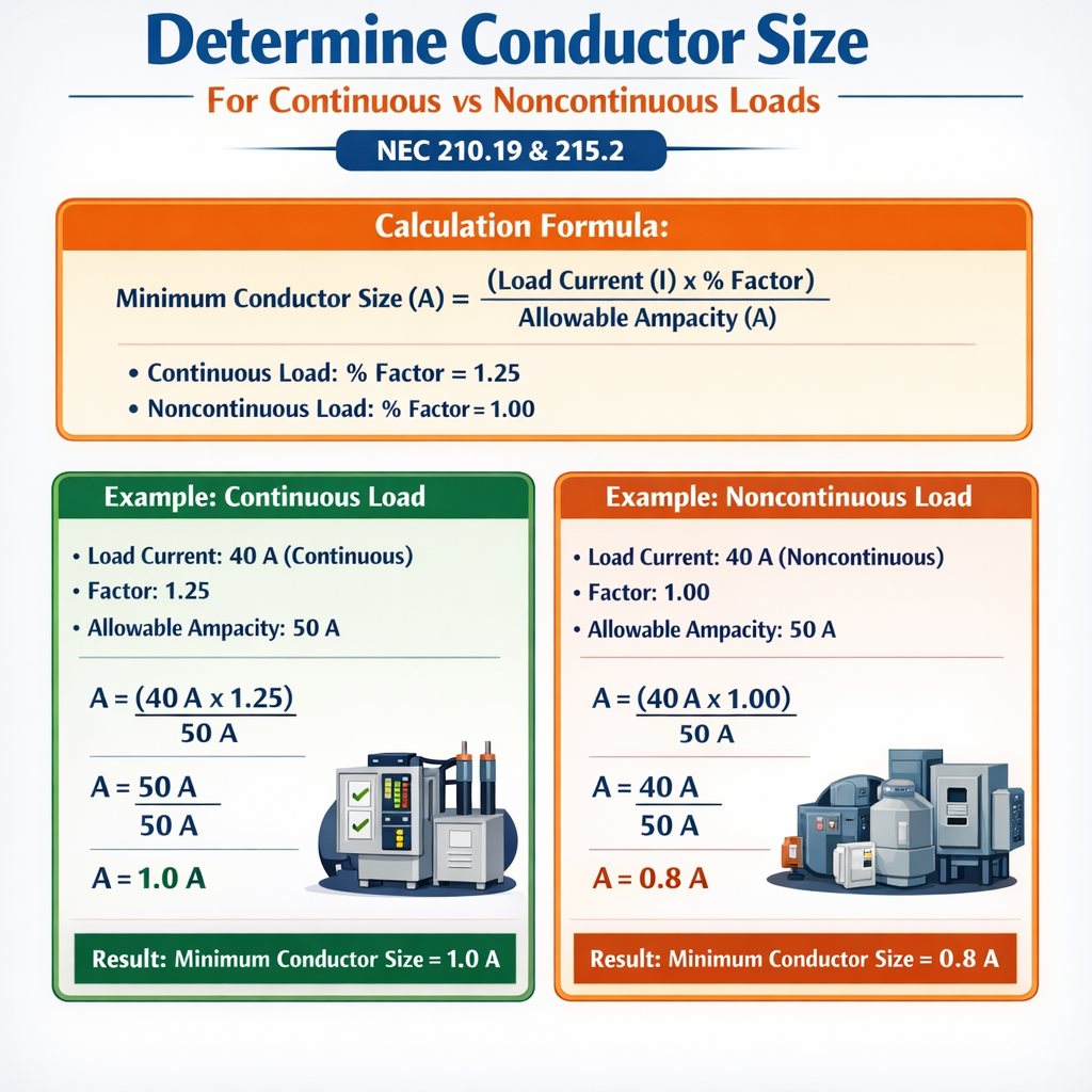
Determine Minimum Conductor Ampacity and Suggested Size for Continuous vs Noncontinuous Loads (NEC 210.19 / 215.2)
Scope and Applicable Code Sections
This document addresses conductor-sizing principles under the National Electrical Code (NEC) focused on continuous versus noncontinuous loads, highlighting NEC 210.19 and 215.2 requirements. It outlines calculation logic used in free calculators and explains required multipliers, adjustment factors, and conductor selection considerations for both single-phase and three-phase systems.
Key Definitions and Regulatory Requirements
Continuous vs Noncontinuous Loads
- Continuous load: A load where the maximum current is expected to continue for three hours or more (NEC definition).
- Noncontinuous load: A load that does not meet the three-hour criterion; sizing and multipliers differ accordingly.
Relevant NEC Sections
- NEC 210.19 — Branch-circuit conductors: design and ampacity considerations.
- NEC 215.2 — Feeder conductor ampacity requirements relative to loads and continuous operation.
- NEC 110.14(C) and 310.15 — Terminals and conductor ampacity columns; use the terminal rating column appropriate to equipment (60°C, 75°C, or 90°C).
Use official NEC publications and the authority having jurisdiction (AHJ) for final approval. See references at the end for authoritative links.
Fundamental Sizing Principles
Overview of the Calculation Sequence
- Determine load power (P) in watts or load current (I) in amperes; identify whether the load is continuous.
- For motors or complex loads, determine power factor (PF) and efficiency if required.
- Convert power to current using the appropriate formula (single-phase or three-phase).
- If the load is continuous per NEC, multiply the computed current by 125% (1.25) to obtain required conductor ampacity.
- Apply conductor ampacity adjustment factors (ambient temperature, bundling/number of conductors, correction factors for insulation temperature rating).
- Select conductor size whose adjusted ampacity meets or exceeds the required ampacity; coordinate with overcurrent-protection device selection.
Basic Formulas (HTML-only)
Single-phase current:
Three-phase current (line current):
Continuous-load conductor ampacity requirement:
When selecting an overcurrent device (OCPD) protective rating (breaker or fuse):
Choose OCPD such that: OCPD rating ≥ Load current (for noncontinuous) or OCPD rating ≥ Required ampacity (for continuous), and OCPD rating ≤ Conductor allowable limits per NEC rules (see 240.4 and 240.6).
Explanation of Variables and Typical Values
- P — Real power in watts (W). Typical values: small appliances (100–3000 W), HVAC units (1–20 kW), industrial motors (1–200 kW).
- V — Line-to-line voltage in volts (V). Typical values: residential 120/240 V single-phase, commercial/industrial 208 V, 480 V, 600 V three-phase systems.
- PF — Power factor (unitless). Typical PF: 0.8–0.95 for motors and inductive loads; 0.95–1.0 for resistive heating.
- √3 — Square root of 3 (approx. 1.732) for three-phase power calculations.
- I — Line current in amperes (A).
Adjustment and Correction Factors
Continuous Load Multiplier
NEC requires conductors supplying continuous loads to have ampacity not less than 125% of the continuous load current: multiply continuous current by 1.25.
Ambient Temperature and Number of Conductors
Two main types of adjustments can affect the required conductor ampacity:
- Ambient temperature correction factors (apply when ambient differs from the base column temperature of the ampacity table; see NEC Table 310.15(B)(2)(a)).
- Adjustment factors for more than three current-carrying conductors in a raceway or cable (see NEC 310.15(B)(3)(a)).
| Condition | Typical Multiplier / Effect | Reference |
|---|---|---|
| Continuous load | ×1.25 required conductor ampacity | NEC 210.19(A), 215.2 |
| Ambient temperature (example multipliers) | Varies by conductor insulation rating; e.g., 30°C baseline: 86%–100% for higher ambient temperatures | NEC Table 310.15(B)(2)(a) |
| More than three current-carrying conductors | Typical multipliers: 4–6 conductors = 0.80; 7–9 = 0.70; 10–20 = 0.50 (consult NEC Table) | NEC 310.15(B)(3)(a) |
Note: The numeric multipliers above are illustrative; always consult the specific NEC table applicable to the installation and the conductor insulation temperature rating.
Common Practice Conductor and Breaker Mapping
The following table shows a practical mapping between common overcurrent protective device ratings and commonly used minimum copper conductor AWG sizes in typical installations. This is a field-practice orientated table—verify ampacities against NEC Table 310.15(B)(16) and equipment terminal ratings before final selection.
| Common OCPD Rating (A) | Common Minimum Copper Conductor AWG (typical) | Usage Notes |
|---|---|---|
| 15 A | 14 AWG | General branch circuits lighting/outlets |
| 20 A | 12 AWG | Small appliance circuits |
| 30 A | 10 AWG | Clothes dryers, small loads |
| 40 A | 8 AWG | Some HVAC or small EV chargers |
| 50 A | 6 AWG | Ranges, larger EV chargers, water heaters |
| 60 A | 6 AWG | Serviceable for many motors and feeders; verify ampacity |
| 100 A | 3 AWG or 2 AWG (site-specific) | Feeder circuits; confirm insulation column |
| 200 A | 2/0 AWG | Service entrances and main feeders |
Important: These mappings are typical practice but are not a substitute for checking exact ampacity tables. Use the conductor insulation rating and terminal temperature rating to select the proper ampacity column.
Calculator Logic and Implementation Notes
Essential Steps for a Free Calculator
- Input required fields: P (W) or I (A), system type (single-phase or three-phase), V (line-to-line voltage), PF (if P given), continuous flag (yes/no), number of current-carrying conductors, ambient temperature, conductor insulation temperature rating (60°C/75°C/90°C).
- If P given and PF known: compute I using the formulas above.
- If continuous: compute Required ampacity = I × 1.25.
- Apply ambient temperature correction factor: Adjusted ampacity = Required ampacity / TempMultiplier (where TempMultiplier is less than or equal to 1 depending on ambient).
- Apply conductor bundling multiplier: Adjusted ampacity = Adjusted ampacity / BundlingMultiplier.
- Find the smallest standard conductor size with ampacity (from the ampacity table column matching insulation rating) ≥ Adjusted ampacity. Provide recommended OCPD options consistent with 240.4 rules and NEC allowed tolerances.
- Generate warning flags if assumed terminal rating is lower than table column or if calculations hit ambiguous boundaries (e.g., locked rotor currents for motors require different consideration).
Edge Cases to Handle
- Motors and motor controllers: size conductors for continuous load plus include motor nameplate and NEC 430 rules (not just load power).
- Inrush/starting currents: do not size conductors solely based on inrush; use motor branch-circuit rules.
- Multiple loads on a branch/feeder: sum continuous loads and apply demand factors where allowed by NEC.
Two Full Worked Examples with Detailed Solutions
Example 1 — Single-Phase Continuous Load (Residential Water Heater Bank)
Scenario: Three electric water heaters installed in parallel, each rated 4.0 kW, connected to a 240 V single-phase supply. They are expected to be operational simultaneously for longer than three hours (continuous). Determine required conductor ampacity and recommend a conductor size and overcurrent device.
Step 1 — Calculate total power:
Step 2 — Convert to current (single-phase):
Step 3 — Apply continuous-load multiplier:
Step 4 — Apply ambient or bundling adjustments (assume normal conditions: no bundling, ambient within table limits):
Step 5 — Select conductor: choose the next standard conductor with ampacity ≥ 62.50 A. Typical practical selection (verify ampacity table and terminal rating): 6 AWG copper is commonly used for 60–65 A service; since 62.5 A required, select 6 AWG copper if the 6 AWG ampacity in the applicable column is ≥ 62.5 A. If the 6 AWG ampacity column (per selected insulation and terminal rating) is only 60 A, then choose 4 AWG copper.
Recommendation: Use 6 AWG copper if the chosen ampacity column gives ≥ 65 A for 6 AWG (e.g., 75°C column often allows higher ampacity). Otherwise, use 4 AWG copper. Use an overcurrent device rated to protect the conductor; the OCPD rating should be the standard size that protects the conductor and meets NEC 240 requirements. For example, if using 6 AWG copper with ampacity 65 A, an OCPD of 70 A may be used only if permitted by conductor rules; otherwise, a 60 A OCPD would be undersized for required 62.5 A. Therefore choose conductor/OCPD combination so that OCPD rating ≥ continuous-load current and conductor ampacity ≥ OCPD rating.
Notes: Verify terminal temperature rating and Table 310.15(B)(16) values. If a 60 A breaker were selected, it would be undersized for the required 62.5 A conductor ampacity requirement for continuous load; therefore select conductor and OCPD to conform.
Example 2 — Three-Phase Continuous Motor Load (Commercial HVAC)
Scenario: A commercial HVAC variable-frequency-drive-fed motor with continuous rated input power of 30 kW at 480 V three-phase, PF = 0.90. Determine conductor ampacity requirement and select a conductor size.
Step 1 — Given: P = 30000 W; V = 480 V; PF = 0.90; three-phase system.
Step 2 — Compute line current:
Step 3 — Continuous-load multiplier:
Step 4 — Adjustment factors: assume the motor feeder runs through a conduit with 5 current-carrying conductors (3 phase + neutral + ground? Typically ground not counted as current-carrying; assume 3 current-carrying conductors). If only 3 current-carrying conductors, no bundling derating applies. Assume ambient temperature and termination rating permit use of the 75°C column with nominal ampacities.
Step 5 — Select conductor: required ampacity ≈ 50.21 A. Standard practice selects 8 AWG copper for many 40–55 A circuits; verify that 8 AWG copper ampacity in the chosen column is ≥ 50.21 A. Typically 8 AWG copper has an ampacity of around 50 A–55 A depending on table column; if the ampacity meets the requirement, choose 8 AWG. Otherwise choose 6 AWG.
Recommendation: If 8 AWG copper in the applicable ampacity column ≥ 50.21 A, select 8 AWG. Choose an overcurrent device consistent with the conductor (e.g., 50 A or next acceptable standard OCPD consistent with NEC rules). If the selected OCPD must be greater than 50.21 A, ensure conductor ampacity matches the OCPD rating, or employ 6 AWG conductor to allow higher OCPD ratings.
Notes: Motor branch-circuit protection under NEC Article 430 may permit specific higher OCPD settings for starting currents; consult Article 430 for protective device sizing and conductor rules for motors.
Practical Tips and Common Pitfalls
- Always use the ampacity column corresponding to the lowest of: conductor insulation rating, equipment terminal temperature rating, and overcurrent device specification.
- For continuous loads, remember the 125% conductor rule; do not confuse this with breaker sizing, which may have separate allowances in NEC 240 and Article-specific accommodations.
- When multiple loads share a feeder, apply NEC demand factors where permitted; do not simply sum nameplate currents for feeders unless NEC requires.
- Ambient temperature, conductor bundling, and correction factors can change the final conductor selection—include these in any automated calculator logic.
- For motors and controllers, follow NEC Article 430 for conductor sizing, short-circuit, and instantaneous trip settings; motor starting currents are not used to size conductors directly except where Article 430 prescribes.
References and Authoritative Links
- NFPA 70, National Electrical Code — official publication and code text (purchase or view through NFPA): https://www.nfpa.org/NEC
- NEC Article 210 — Branch Circuits (see 210.19 for conductor sizing guidance): https://www.nfpa.org/NEC
- NEC Article 215 — Feeders (see 215.2 for feeder conductor ampacity rules): https://www.nfpa.org/NEC
- NEC Table 310.15(B)(16) (formerly 310.16) — conductor ampacities: refer to official NEC tables to determine allowable ampacity by conductor size and insulation column.
- IEEE and NEMA publications on conductor thermal ratings and installation practice: https://www.ieee.org and https://www.nema.org
- International Association of Electrical Inspectors (IAEI) guidance and commentary: https://www.iaei.org
Verification Checklist Before Finalizing Conductor Selection
- Confirm load classification: continuous vs noncontinuous.
- Verify voltage, phase, and power factor entries.
- Compute current using appropriate single-phase or three-phase formula.
- Apply 125% for continuous loads.
- Apply ambient temperature and conductor bundling correction factors.
- Cross-check conductor ampacity in the NEC ampacity table column matching terminal rating and insulation type.
- Select conductor and OCPD such that the OCPD protects conductor and complies with NEC 240 and applicable Article-specific exceptions.
- Document assumptions (temperature, PF, simultaneous operation) for AHJ review.
Final Notes on International Usage
Although this article references NEC sections, the calculation principles (power-to-current conversion, continuous-load multiplier, ambient/bundling corrections) apply internationally. Local codes (IEC, local electrical regulations) may use different tables or require different multipliers; always verify with the applicable national standard and the authority having jurisdiction.
If you plan to implement a free online calculator, include fields to capture insulation rating, terminal rating, ambient temperature, number of current-carrying conductors, and whether loads are continuous. Present warnings where code-based exceptions or motor-specific rules apply, and include links to NEC or local code references for users to validate results.