Accurate neutral load calculations prevent feeder panel imbalances and neutral overheating in mixed 120/240V systems.
This guide provides technical methods, formulas, examples, and code-referenced practices for preventing feeder neutral overloads.
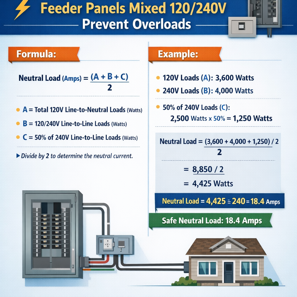
Neutral Load Calculator for 120/240 V Split-Phase Feeders (Mixed 120/240 V Loads, Overload Prevention)
Fundamental principles of neutral current in mixed 120/240V feeders
In North American split-phase 120/240V systems, two 120V legs (L1 and L2) are 180° out of phase. Loads connected line-to-neutral on L1 and L2 generate currents that may cancel in the neutral if magnitudes are equal and phase-opposed. Neutral current becomes the vector sum of all line-to-neutral currents and, for purely sinusoidal linear loads, the neutral magnitude equals the absolute difference of the instantaneous phasor sums of each phase.
When non-linear loads (electronic ballasts, variable speed drives, computer equipment) produce harmonic currents, the neutral can carry significantly higher RMS currents, particularly due to triplen (3rd, 9th, 15th, ...) harmonics, which add arithmetically on the neutral in multi-phase systems.
Key risks and engineering objectives
- Prevent neutral conductor overheating and insulation degradation.
- Ensure overcurrent protection devices coordinate for neutral and phase conductor demands.
- Calculate accurate neutral ampacity including continuous load multipliers and harmonic magnification factors.
- Provide clear, reproducible methods to size neutral conductors and to specify neutral monitoring in feeder panels.
Mathematical formulas and variable definitions
Below are the primary formulas used in neutral load calculations for mixed 120/240V split-phase feeders. Each formula is given in plain HTML text. After each formula the variables are explained with typical values.
1) Line current for a single-phase load
- I: line current (A).
- P: active power (W). Typical values: lighting 60–150 W per fixture, computer rack 1000–5000 W.
- V: line-to-neutral voltage (120 V for split-phase single-phase loads).
- PF: power factor (0.8–1.0 typical; motors lower during startup).
2) Neutral current for purely linear split-phase loads (phasor cancellation)
- I_N: neutral current magnitude (A) when loads are purely sinusoidal and 180° apart.
- I_L1, I_L2: summed line currents on phase 1 and phase 2 respectively (A).
- Typical case: if I_L1 = 30 A and I_L2 = 20 A, then I_N = 10 A.
3) General phasor neutral current (vector form)
- I1, I2: magnitudes of phase currents (A).
- φ1, φ2: phase angles of currents relative to a reference (radians or degrees).
- Typical: for PF differences or unsymmetrical loads, cos(φ1 − φ2) may change neutral magnitude by ±.
4) Harmonic-rich neutral current for triplen harmonics
- I_basic_N: neutral due to fundamental (A), computed per linear formulas above.
- Σ I_triplen: arithmetic sum of triplen harmonic magnitudes (3rd, 9th, 15th, …) present in each phase; they add in the neutral in single-phase three-wire systems.
- Typical: electronic loads often produce 3rd harmonic up to 20–60% of fundamental per device; aggregated triplen can exceed fundamental partial sums.
5) Continuous load adjustment per NEC practice
- I_design: sizing current for continuous loads (A).
- I_load: calculated RMS current (A).
- Typical: continuous loads >3 hours require the 125% multiplier under NFPA 70 (NEC) Article 100 and 110.3(B).
Step-by-step Accurate Neutral Load Calculator methodology
- Inventory loads: list every load on L1, L2 and any 240V loads. Include connected power (W), voltage (120/240 V), power factor (PF), harmonic content (THD% if known), and whether the load is continuous.
- Convert each load to equivalent line currents: use I = P/(V × PF) for single-phase line-to-neutral devices; for 240V loads line current is I = P/(V_line × PF) where V_line = 240 V for two-pole loads.
- Aggregate currents on L1 and L2 separately: sum phasor currents if you have phase angles; otherwise, sum RMS magnitudes for an upper-bound conservative check.
- Compute neutral current for fundamentals: apply I_N = |I_L1 − I_L2| for linear assumption, or phasor equation if phase angles differ.
- Assess harmonic contribution: estimate or measure triplen harmonics; compute Σ I_triplen and combine with fundamental neutral via root-sum-square or additive rule where appropriate.
- Apply continuous load factor: multiply continuous portion by 1.25 when sizing conductors and breakers as required by code.
- Compare neutral current to conductor ampacity and breaker ratings. If I_N exceeds allowable ampacity, increase neutral conductor size, split loads, or redesign to balance phases and mitigate harmonics.
- Document calculations and provide monitoring provisions (neutral current trip threshold, thermal sensors) for final design verification in service.
Tables of common loads, currents and conductor ampacities
The following tables provide frequently used load values and common conductor ampacities for design checks. Use these as baseline reference; always confirm with site measurements and code tables.
| Load Type | Voltage | Typical Power (W) | Typical Current (A) | Notes |
|---|---|---|---|---|
| General lighting (LED fixture) | 120 V | 30–100 | 0.25–0.83 | PF ≈ 0.9–0.98 |
| Receptacle (small appliances) | 120 V | 500–1500 | 4.2–12.5 | Intermittent, PF ≈ 0.95 |
| Dryer (electric) | 240 V | 3000–6000 | 12.5–25 | Two-pole load, PF ≈ 1.0 |
| Electric range | 240 V | 8000–12000 | 33–50 | May have multi-circuit loads and diversity |
| Water heater (resistive) | 240 V | 3500–5500 | 14.6–22.9 | Continuous; consider 125% factor |
| Central HVAC (compressor) | 240 V | 3000–20000 | 12.5–83.3 | Inrush currents high; motor PF low during start |
| Computer rack (server) | 120 V | 2000–8000 | 16.7–66.7 | Non-linear, high harmonic content |
| Variable frequency drive + motor | 480/240 V | Depends | Varies | Produce triplen and other harmonics |
| Conductor (Copper, THHN) | Common Ampacity (A) | Typical Use |
|---|---|---|
| 14 AWG | 15 | Branch circuits lighting (120 V) |
| 12 AWG | 20 | General-purpose receptacles |
| 10 AWG | 30 | Small appliances, water heater circuits |
| 8 AWG | 50 | Small electric ranges, subpanel feeders |
| 6 AWG | 65 | Large appliances, feeder conductors |
| 4 AWG | 85 | Main feeders for small commercial |
| 3/0 AWG | 200 | Main service conductors |
Note: Ampacity values vary with insulation rating, temperature correction, bundling and local code; reference NEC Table 310.15(B)(16) or local authority having jurisdiction for final conductor sizing.
Practical calculation considerations and conservative assumptions
- When phase angles are unknown, use magnitude algebra (I_N = |I_L1 − I_L2|) for linear balance; for safety, assume worst-case phasing that increases neutral current.
- For unknown harmonic content assume a harmonic magnification factor (HMF) based on load type: 1.0 for purely linear, 1.2–1.5 for moderate electronic loads, >2.0 for high-density data centers without harmonic mitigation.
- Apply continuous load multiplier 125% to continuous portions before comparing to conductor ampacity and breaker ratings.
- Consider separate neutrals for circuits with high nonlinearities where triplen harmonics might overload a shared neutral.
- Where multiple single-phase nonlinear loads exist, include harmonic contribution explicitly: measure with power quality analyzer for high-accuracy designs.
Example 1: Residential split-phase panel calculation — full development
Scenario: A single-family home has the following connected loads on a feeder panel (all values RMS):
- L1 circuits: lighting 12 fixtures @ 60 W each (120 V), kitchen small appliances 1500 W continuous, one computer load 2000 W (120 V, non-linear, 30% 3rd harmonic of fundamental magnitude), and a dryer 5000 W (240 V).
- L2 circuits: lighting 10 fixtures @ 60 W each (120 V), living room receptacles 2000 W, refrigerator 800 W (120 V), and water heater 4500 W (240 V, continuous).
Step 1 — Convert single-phase loads to currents (fundamental):
Lighting L1: P = 12 × 60 = 720 W. I_light_L1 = 720 / (120 × 0.95) ≈ 6.32 A
Computer rack (non-linear): fundamental I_comp = 2000 / (120 × 0.95) ≈ 17.54 A; 3rd harmonic magnitude I_3_comp ≈ 0.30 × 17.54 ≈ 5.26 A (added to neutral later)
Dryer (240 V two-pole): I_dryer = 5000 / (240 × 1.0) ≈ 20.83 A (no neutral contribution for pure 240 V resistive load)
Lighting L2: P = 10 × 60 = 600 W. I_light_L2 = 600 / (120 × 0.95) ≈ 5.26 A
Step 2 — Aggregate L1 and L2 fundamental currents:
Step 3 — Fundamental neutral due to line currents (linear assumption):
Step 4 — Add triplen harmonic contribution to neutral: Only the computer load produces a 3rd harmonic of approximately 5.26 A. Triplen harmonics from L1 phases add (L2 triplen assumed negligible here), so neutral triplen sum ΣI_triplen ≈ 5.26 A.
Combine fundamentals and triplen contributions (root-sum-square conservative):
I_N_total = sqrt( I_N_fundamental^2 + ΣI_triplen^2 ) = sqrt(7.20^2 + 5.26^2) ≈ sqrt(51.84 + 27.66) ≈ sqrt(79.5) ≈ 8.92 A
Step 5 — Apply continuous load factor on continuous loads that affect phase currents for sizing conductors: water heater (L2) and kitchen appliance (L1) are continuous. Adjusted currents:
I_wh_adj contributes to line currents for 240 V branch but not neutral. Recompute I_L1_total_adj = 6.32 + 16.45 + 17.54 = 40.31 A
Step 6 — Compare to neutral conductor ampacity and select neutral size: A 12 AWG copper conductor has 20 A ampacity and would be acceptable by magnitude, but consider risk, future loads, and harmonic heating. For service feeder a 10 AWG or 8 AWG neutral may be selected depending on code and derating. If selecting 12 AWG, confirm derating for grouped conductors and ambient temperatures. Common practice: select a neutral matching phase conductor sized for feeder (e.g., 6 AWG for 65 A feeder).
Design comment: The neutral worst-case RMS current of ~11.74 A is modest versus typical branch conductor ampacities; however, if additional non-linear loads are added or the phase imbalance increases, neutral can grow. For robust design choose neutral sized for foreseeable future loads and include harmonic mitigation (filters) if server/computer loads increase.
Example 2: Small office panel with multiple nonlinear loads and harmonic assessment
Scenario: A small office has three identical single-phase UPS-fed racks on L1, each drawing 6 kW at 120 V with PF 0.95 and producing 40% 3rd harmonic relative to their fundamental. L2 hosts general lighting and miscellaneous receptacles totaling 10 kW at 120 V PF 0.95. There is a shared neutral for all single-phase circuits.
Step 1 — Compute fundamental currents:
For each UPS rack: I_fund_per_rack = 6000 / (120 × 0.95) ≈ 52.63 A. Three racks on L1 give I_L1_fund = 3 × 52.63 = 157.9 A.
L2 loads: I_L2_fund = 10000 / (120 × 0.95) ≈ 87.72 A.
Step 2 — Compute neutral fundamental current:
Step 3 — Triplen harmonic contribution: each UPS rack produces I_3_per_rack = 0.40 × 52.63 = 21.05 A (3rd harmonic magnitude). Triplen harmonics from identical single-phase loads on the same two-phase system add algebraically on the neutral (they are in-phase on the neutral).
Step 4 — Combine neutral fundamentals and triplen contribution; because triplen harmonics are at distinct frequency they add in RMS sense with fundamentals, but since triplen are at 3rd harmonic frequency and add arithmetically on neutral, worst-case neutral RMS is:
I_N_total = sqrt( I_N_fundamental^2 + ΣI_triplen^2 ) = sqrt(70.18^2 + 63.15^2) ≈ sqrt(4925 + 3988) ≈ sqrt(8913) ≈ 94.4 A
Step 5 — Continuous load adjustment: UPS loads are effectively continuous. Apply 125%:
Step 6 — Neutral sizing and mitigation: A neutral conductor must have ampacity ≥ 118 A. Typical copper conductor sizes to meet this might be 3 AWG (up to ~100–115 A depending on temp rating) or 2 AWG/1 AWG; consult NEC Table 310.15 for precise ampacities. In practice, select a neutral equal to the phase conductor sized for the feeder, and consider the following mitigations:
- Install 3rd harmonic filters or K-rated transformers that reduce triplen currents.
- Distribute UPS racks across both phases to reduce L1 dominance and lower I_N_fundamental.
- Provide a dedicated neutral or parallel neutrals where allowed, and ensure terminations can handle harmonic heating.
Design conclusion: Without mitigation, the neutral RMS current could exceed phase conductor ratings. This demonstrates the high risk posed by multiple high-density non-linear single-phase loads sharing a neutral. Proper mitigation includes phase redistribution, harmonic filters, or upsizing of neutrals and associated equipment.
Protective devices, monitoring and installation practices
- Neutral conductors are protected indirectly by phase overcurrent devices; a neutral alone cannot have an overcurrent device protecting only neutral except in limited circumstances. Ensure phase overcurrent coordination and neutral ampacity alignment.
- For feeders with high harmonic content, specify K-rated transformers or harmonic mitigating transformers per IEEE Std C57.110 and consult IEEE 519 for harmonic limits and mitigation strategies.
- Install neutral current monitoring relays or thermal sensors in the panel if neutral overheating risk is non-negligible (data centers, hospitals, industrial sites).
- Ensure terminations use hardware rated for expected thermal stress; harmonics increase heating at lugs and bus bars.
Verification, testing and in-service monitoring
- Measure actual neutral and phase currents with a true-RMS power quality analyzer to capture harmonic content.
- Record THD and individual harmonic magnitudes; recompute neutral RMS using measured values, not estimates.
- Perform thermal imaging of bussing and terminations under typical and peak operation to detect hotspots.
- Implement periodic retesting after load changes or equipment additions.
Standards, code references and further reading
Key normative documents and authoritative sources referenced for calculations and design rules include:
- NFPA 70, National Electrical Code (NEC) — especially Article 110, 220 and Table 310.15(B)(16). Authority: https://www.nfpa.org/NEC
- IEEE Std 519 — Recommended Practice and Requirements for Harmonic Control in Electrical Power Systems. Authority: https://ieeexplore.ieee.org
- IEC 60364 — Electrical installations for buildings (for international grounding and wiring practices). Authority: https://www.iec.ch
- IEEE Std C57.110 — Guide for Transformers Subjected to Non-Sinusoidal Waveforms. Authority: https://standards.ieee.org
- Manufacturer data sheets for UPS, VFDs, and transformers for specific harmonic emission data and recommended mitigation.
Best practices summary for preventing neutral overloads in mixed 120/240V feeders
- Perform a complete load inventory and calculate phase currents accurately, including power factors.
- Estimate or measure harmonic content; include triplen harmonics explicitly in neutral calculations.
- Apply the 125% continuous load factor for sizing feeders and neutrals where applicable.
- Select neutral conductor ampacity based on worst-case RMS including harmonics and continuous adjustment.
- Consider harmonic mitigation (filters, K-rated transformers), phase redistribution, and separate neutrals for high non-linear loads.
- Document design decisions and provide field verification with true-RMS analyzers and thermal inspections.
Appendix — Quick-reference formulas and example variable values
Essential quick formulas (repeat for convenience):
- I = P / (V × PF)
- I_N_linear = |I_L1 − I_L2|
- I_N_phasor = sqrt(I1^2 + I2^2 − 2 × I1 × I2 × cos(φ1 − φ2))
- I_N_with_triplen = sqrt(I_N_fundamental^2 + (Σ triplen)^2)
- I_design_continuous = I_calculated × 1.25
Typical variable example values:
- V_line-to-neutral = 120 V
- V_line-to-line (split-phase) = 240 V
- PF linear lighting = 0.95–0.99
- PF motors (running) = 0.8–0.9; during startup PF lower
- Triplen harmonic fraction for common nonlinear loads = 0–0.6 of fundamental magnitude
Final engineering notes
Design for neutral conductors must be conservative when unknowns such as harmonic content, future loads, and continuous operation exist. The Accurate Neutral Load Calculator methodology above yields reliable RMS current estimates when inputs—power, PF, harmonics, and load duty—are accurate. For critical installations, combine calculation-based design with direct site measurements and adopt mitigation strategies early in the design phase.
For authoritative updates and local amendments, always consult the current edition of the NEC and local authority having jurisdiction (AHJ). When in doubt, conduct power quality surveys and involve specialists in harmonics and transformer design.