Variable Frequency Drives (VFDs) are vital in automation, ensuring energy efficiency, motor speed control, and enhanced equipment protection.
Correct VFD sizing per IEC and IEEE standards guarantees performance, longevity, compliance, and operational reliability across industries.
VFD (CVFD) Sizing Calculator — IEC & IEEE
How do I choose ND vs HD?
HD (Heavy Duty, 150%): constant-torque loads (conveyors, mixers, hoists). If unsure, choose HD.
Why oversize on single-phase input?
What about altitude/temperature?
Importance of Correct VFD Sizing
Selecting an undersized VFD may result in:
- Overheating of power electronics
- Nuisance tripping under starting or overload conditions
- Reduced service life of the drive
Conversely, oversizing leads to:
- Unnecessary capital expenditure
- Increased footprint and cooling requirements
- Higher installation costs
Therefore, precise sizing using standardized calculation methods ensures reliability, cost-effectiveness, and compliance.
Common VFD Sizing Parameters
VFD sizing depends on multiple variables, including motor nameplate data, load characteristics, duty cycle, and application type. The most critical factors include:
- Motor Power Rating (kW or HP)
- Rated Voltage (V)
- Full Load Current (FLC, A)
- Starting Torque Requirement
- Service Factor
- Overload Capacity
- Power Supply Characteristics (IEC vs. IEEE, harmonics, derating factors)
- Environmental Conditions (altitude, ambient temperature, cooling method)
Extended Reference Tables for VFD Sizing (IEC / IEEE)
The following table consolidates typical motor ratings, voltages, and full-load currents for 3-phase induction motors (50 Hz IEC and 60 Hz IEEE). These values are widely used for preliminary VFD sizing.
Table 1: Typical IEC/IEEE Motor Ratings and Full Load Currents
| Motor Power (kW) | Power (HP) | Voltage (V) | FLC @ 400 V (A, 50 Hz IEC) | FLC @ 460 V (A, 60 Hz IEEE) |
|---|---|---|---|---|
| 0.75 | 1.0 | 400 / 460 | 1.7 | 1.6 |
| 1.5 | 2.0 | 400 / 460 | 3.2 | 3.0 |
| 2.2 | 3.0 | 400 / 460 | 4.5 | 4.2 |
| 3.0 | 4.0 | 400 / 460 | 6.0 | 5.6 |
| 4.0 | 5.5 | 400 / 460 | 7.8 | 7.2 |
| 5.5 | 7.5 | 400 / 460 | 11.0 | 10.2 |
| 7.5 | 10 | 400 / 460 | 15.2 | 13.8 |
| 11 | 15 | 400 / 460 | 22.0 | 20.0 |
| 15 | 20 | 400 / 460 | 29.0 | 26.0 |
| 18.5 | 25 | 400 / 460 | 35.0 | 32.0 |
| 22 | 30 | 400 / 460 | 41.0 | 38.0 |
| 30 | 40 | 400 / 460 | 55.0 | 50.0 |
| 37 | 50 | 400 / 460 | 68.0 | 61.0 |
| 45 | 60 | 400 / 460 | 82.0 | 73.0 |
| 55 | 75 | 400 / 460 | 102.0 | 89.0 |
| 75 | 100 | 400 / 460 | 138.0 | 124.0 |
| 90 | 125 | 400 / 460 | 162.0 | 146.0 |
| 110 | 150 | 400 / 460 | 198.0 | 178.0 |
| 132 | 175 | 400 / 460 | 238.0 | 214.0 |
| 160 | 215 | 400 / 460 | 286.0 | 258.0 |
| 200 | 270 | 400 / 460 | 358.0 | 320.0 |
| 250 | 335 | 400 / 460 | 448.0 | 400.0 |
| 315 | 425 | 400 / 460 | 566.0 | 506.0 |
| 400 | 540 | 400 / 460 | 720.0 | 640.0 |
Engineers typically size the VFD 10–20% above motor full load current to account for overloads and service conditions.
Essential Formulas for VFD Sizing
The following formulas are standardized references for IEC / IEEE-compliant VFD sizing.
1. Motor Power Formula
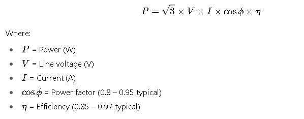
2. Full Load Current (FLC)
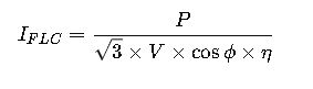
Common values:
- Power factor: 0.85 (standard IEC motors)
- Efficiency: 0.90 – 0.95 for medium-size motors
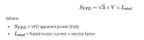
3. VFD Rating (kVA)
4. Overload Capacity (per IEC 61800-2)
VFDs must withstand 150% rated current for 60 s or 180% for 10 s, depending on duty class.

5. Derating Factors
At higher temperatures and altitudes, VFDs require derating:
- Temperature:
- 40°C: No derating
- 50°C: –10% capacity
- 60°C: –20% capacity
- Altitude:
- Up to 1000 m: No derating
- 2000 m: –10%
- 3000 m: –20%
Derated VFD power:
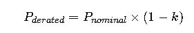
Where k = derating factor.
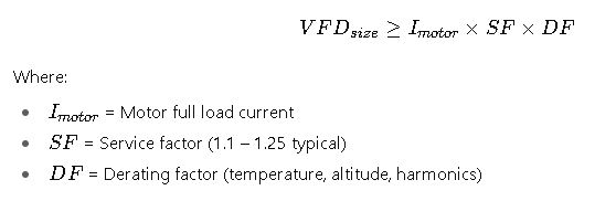
6. VFD Selection Formula
Practical Considerations in VFD Sizing According to IEC and IEEE
When designing a VFD system, engineers must not only rely on motor nameplate data but also evaluate the operating environment, load characteristics, and duty cycle. International standards like IEC 61800 and IEEE 519 emphasize that drives should be selected considering:
- Load type (constant torque, variable torque, or constant power).
- Acceleration and deceleration demands (e.g., conveyors vs. pumps).
- Harmonic impact on the electrical network.
- Cooling and ambient conditions (temperature, humidity, dust, altitude).
- Protection coordination (circuit breakers, fuses, contactors).
Correct evaluation ensures that the VFD provides long-term reliability and compliance with international codes.
Common Load Categories and Their Impact on VFD Sizing
1. Variable Torque Loads
- Applications: Pumps, fans, blowers.
- Torque demand increases with the square of the speed.
- VFDs in these applications can often be sized at 100% of motor FLC.
2. Constant Torque Loads
- Applications: Conveyors, mixers, crushers, positive displacement pumps.
- Torque requirement is independent of speed.
- Drives should be sized with 10–20% margin above motor FLC.
3. Constant Power Loads
- Applications: Winders, spindles, machining centers.
- Torque decreases as speed increases.
- Typically require specialized vector-control VFDs with higher overload ratings.
Environmental and Installation Factors Affecting VFD Sizing
- Altitude
- Above 1000 m, air density decreases, reducing cooling efficiency.
- IEC recommends derating, typically 1% per 100 m above 1000 m.
- Ambient Temperature
- Drives are rated for 40°C operation.
- For each 10°C increase above rated conditions, derating is mandatory.
- Harmonic Distortion (IEEE 519 compliance)
- Non-linear VFD loads introduce current harmonics.
- Engineers may need input line reactors, harmonic filters, or 12-pulse rectifiers.
- Ingress Protection (IP Rating)
- IEC 60529 defines IP codes for dust and moisture protection.
- Indoor drives often require IP20/IP21, while outdoor or dusty environments demand IP55/IP66.
Real-World Application Cases of VFD Sizing
Case Study 1: Pumping Station (Variable Torque Application)
Scenario:
A water treatment plant requires VFDs for three centrifugal pumps rated at 55 kW, 400 V, 50 Hz IEC motors. The site is located at 1500 m altitude with a maximum ambient temperature of 45°C.
Step-by-step evaluation:
- Motor full load current (FLC) from tables: ~102 A.
- Since it is a variable torque load, drive sizing ≈ motor FLC.
- Derating for altitude (1500 m ≈ –5%).
- Derating for temperature (45°C ≈ –5%).
- Effective derating: ≈ –10%.
- Adjusted current requirement: 102 A ÷ (1 – 0.10) ≈ 113 A.
- Nearest VFD rating: 132 kW frame (as 110 kW VFD may be borderline).
Result:
The engineering team selects a 132 kW IEC-compliant VFD to ensure reliable operation and future expansion capacity.
Key insights:
- Even though the motor is 55 kW, derating and environmental conditions pushed the drive selection higher.
- Properly sized VFD prevents nuisance trips and extends equipment life.
Case Study 2: Industrial Conveyor (Constant Torque Application)
Scenario:
An iron ore conveyor system requires a 200 kW, 460 V, 60 Hz IEEE motor, operating under heavy start-stop duty with high torque demand.
Step-by-step evaluation:
- Motor FLC from tables: ≈ 320 A.
- Constant torque loads require oversizing of 15–20%.
- Required current capacity: 320 A × 1.20 = 384 A.
- Overload conditions: conveyor requires 150% current for 60 s, which must be supported by VFD.
- The environment is standard (40°C, <1000 m altitude).
- IEEE-compliant VFD nearest standard rating: 250 kW (400 A).
Result:
A 250 kW IEEE-rated VFD is selected, ensuring compliance with IEEE 112 motor performance and IEC 61800 overload requirements.
Key insights:
- Constant torque loads place significant stress on drives.
- The engineer must consider overload and torque ripple suppression.
Extended Recommendations for VFD Sizing
- Select VFD by Current, Not Power
- Always match drive current capacity to motor FLC, not just kW/HP rating.
- Power ratings vary across regions (IEC vs. NEMA motors).
- Account for Motor Service Factor
- IEC motors typically have SF = 1.0–1.1, while NEMA motors allow SF = 1.15–1.25.
- Drives must handle these higher currents during overload.
- Evaluate Starting Torque
- High-inertia loads (e.g., centrifuges, crushers) require vector-control VFDs with torque boost.
- Consider Efficiency Standards
- Motors are now rated under IEC 60034-30 (IE2, IE3, IE4 classes).
- High-efficiency motors reduce FLC, but drive must still meet transient loads.
- Harmonics and Power Quality
- In compliance with IEEE 519, drives >75 kW should include harmonic mitigation strategies.
- This ensures grid compatibility and prevents transformer overheating.
- Safety and Protection
- Integrate short-circuit protection, ground fault monitoring, and motor thermal sensors.
- IEC 60204-1 and IEEE 1566 provide guidelines for protection coordination.
Extended Reference Resources
For deeper technical validation, engineers should consult:
- IEC 61800 – Adjustable speed electrical power drive systems.
- IEC 60034 – Rotating electrical machines.
- IEEE 112 – Standard Test Procedure for Polyphase Induction Motors.
- IEEE 519 – Recommended Practices for Harmonic Control in Electrical Power Systems.
- NFPA 70 (NEC) – U.S. National Electrical Code for drive installations.
- IEEE 1566 – Performance requirements for adjustable speed drives.