Understanding transformer impedance percentage is essential in electrical engineering, enabling precise design, fault analysis, and stability evaluation. The Transformer Impedance Percentage Calculator – IEEE, IEC quantifies impedance characteristics, ensuring reliable performance across grid and industrial applications.
Transformer Impedance Percentage Calculator (IEC & IEEE)
What Is Transformer Impedance Percentage?
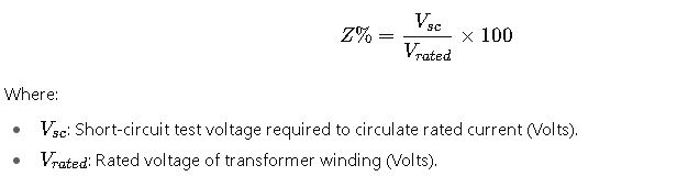
The impedance percentage of a transformer, also called per-unit impedance (Z%), represents the voltage drop across the transformer under rated load, expressed as a percentage of the rated voltage. It also directly determines the short-circuit current at the transformer’s secondary terminals.
In practice:
- High impedance percentage (e.g., 10%–15%) → reduces fault current but increases voltage drop under load.
- Low impedance percentage (e.g., 4%–6%) → improves voltage regulation but increases short-circuit current levels.
IEEE and IEC standards define recommended ranges depending on transformer size, cooling method, and voltage class.
Extended Table of Common Transformer Impedance Percentages (IEEE, IEC)
The following table compiles typical transformer impedance values based on international standards and manufacturer data. These values are frequently encountered in distribution, industrial, and power transformers.
| Transformer Rating (MVA) | Voltage Class (kV) | Cooling Type (ONAN/ONAF/ODAF) | Typical Z% (IEC) | Typical Z% (IEEE) | Standardized Range |
|---|---|---|---|---|---|
| 0.5 – 2.5 | ≤ 15 | ONAN | 4.0 – 5.0 | 4.5 – 5.5 | 4 – 6% |
| 2.5 – 10 | ≤ 36 | ONAN / ONAF | 5.0 – 6.5 | 5.5 – 7.0 | 5 – 7% |
| 10 – 25 | 36 – 72.5 | ONAN / ONAF | 6.0 – 7.5 | 6.0 – 8.0 | 6 – 8% |
| 25 – 50 | 72.5 – 145 | ONAF | 7.0 – 9.0 | 7.5 – 9.5 | 7 – 10% |
| 50 – 100 | 145 – 245 | ONAF / ODAF | 9.0 – 10.5 | 9.0 – 11.0 | 9 – 11% |
| 100 – 250 | 245 – 400 | ODAF | 10.0 – 11.5 | 10.5 – 12.5 | 10 – 12% |
| 250 – 500 | 400 – 765 | ODAF / OFAF | 11.0 – 12.5 | 11.0 – 13.0 | 11 – 13% |
| > 500 | 765+ | OFAF / ODAF / OFWF | 12.0 – 14.0 | 12.0 – 14.0 | 12 – 14% |
Notes:
- ONAN: Oil Natural Air Natural.
- ONAF: Oil Natural Air Forced.
- ODAF: Oil Directed Air Forced.
- OFAF/OFWF: Oil Forced with Air or Water Cooling.
These values may vary by manufacturer, design optimization, and country-specific regulations, but they provide benchmark reference points for calculations.
Key Formulas for Transformer Impedance Percentage – IEEE, IEC
1. Percentage Impedance (Z%)
Typical Values:
- Distribution transformers: 4–6%.
- Medium power transformers: 6–10%.
- Large power transformers: 10–14%.
2. Equivalent Per-Unit Impedance
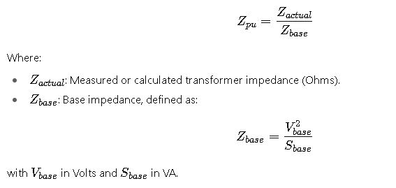
Purpose: Ensures standardized comparison across transformers of different ratings.
3. Short-Circuit Current from Impedance
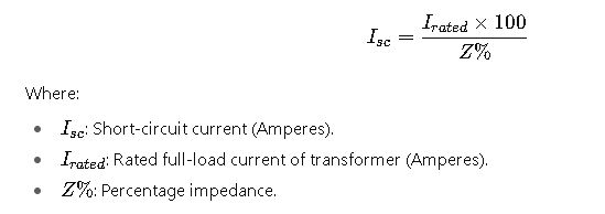
Implication: Lower impedance → higher fault current.
4. Voltage Regulation Approximation
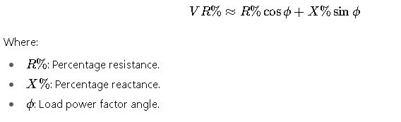
5. Separation of Resistance and Reactance
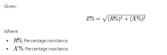
Manufacturers often specify R% and X% separately for precision.
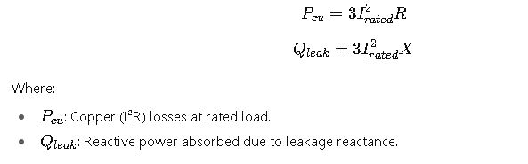
6. Real and Reactive Power Losses
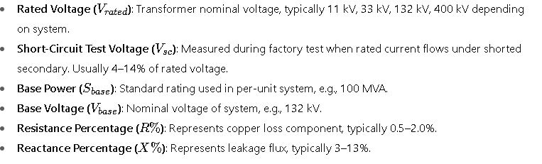
Detailed Explanation of Variables
Practical Applications of Transformer Impedance Percentage
The concept of transformer impedance percentage is not just theoretical—it directly affects power system performance, protection coordination, and stability margins. Both IEEE and IEC standards emphasize impedance calculation because:
- It defines the magnitude of fault currents during short circuits.
- It determines voltage drop under load conditions.
- It affects parallel operation of transformers—only units with compatible impedances can share load proportionally.
- It influences arc flash studies, relay coordination, and equipment rating selection.
Real-World Case Study 1: Distribution Transformer in an Industrial Facility
Scenario:
An industrial plant in North America requires a 5 MVA, 13.8/0.48 kV distribution transformer. The utility demands that the transformer’s impedance percentage meet IEEE C57.12.00 guidelines to ensure fault current limitations.
Key Data:
- Transformer rating: 5 MVA.
- Primary voltage: 13.8 kV.
- Secondary voltage: 480 V.
- Utility specification: minimum 5% impedance.
Step-by-Step Engineering Approach (without formulas):
- The engineering team identifies that if impedance is too low, fault currents will exceed breaker ratings.
- If impedance is too high, the plant will experience excessive voltage drops during motor starts.
- Based on IEEE recommendations, the transformer manufacturer offers an impedance of 5.75%.
- Short-circuit analysis confirms that this value keeps fault levels below the switchgear rating while maintaining voltage regulation within ANSI C84.1 limits.
Outcome:
- The transformer operates safely.
- Protective relays coordinate correctly with utility requirements.
- Equipment cost is optimized because breakers do not need oversized fault current ratings.
Real-World Case Study 2: Power Grid Interconnection Transformer
Scenario:
A European transmission operator must install a 250 MVA, 400/132 kV transformer to interconnect two grid sections. The design follows IEC 60076-5 requirements.
Key Data:
- Transformer rating: 250 MVA.
- Primary voltage: 400 kV.
- Secondary voltage: 132 kV.
- IEC recommended impedance: 12%.
Engineering Approach:
- Grid stability studies show that a lower impedance transformer would lead to excessively high short-circuit currents at 132 kV substations.
- A higher impedance transformer would worsen voltage regulation, making it difficult to maintain ±5% voltage stability.
- A value of 12.5% impedance is selected, balancing both protection and operational flexibility.
- This choice ensures that protective relays, fault limiters, and circuit breakers all operate within their design ratings.
Outcome:
- Fault current levels are manageable within IEC breaker capabilities.
- Grid voltage remains stable during load changes.
- Compliance with ENTSO-E grid codes is achieved.
Extended List of Engineering Impacts of Transformer Impedance Percentage
- Short-Circuit Levels: Determines whether breakers, fuses, and relays are adequately rated.
- Voltage Regulation: Affects motor starting, lighting stability, and sensitive electronic loads.
- Transformer Parallel Operation: Only transformers with similar impedance percentages can share load effectively.
- System Protection: Impedance influences coordination studies in ETAP, DIgSILENT PowerFactory, and PSCAD software.
- Arc Flash Hazards: Higher short-circuit currents increase arc flash incident energy.
- Economic Impact: Correct impedance selection avoids oversizing protective devices, saving CAPEX.
- Reliability: Grid stability and industrial uptime depend on precise impedance matching.
Common Values in Industry Practice
To make this guide more practical, the following table summarizes impedance percentages typically encountered in field applications, according to IEEE and IEC data.
| Transformer Type | Typical Rating | Common Z% Range | Industry Notes |
|---|---|---|---|
| Pole-mounted distribution units | 25 – 500 kVA | 4.0 – 6.0% | Lower values preferred for better regulation. |
| Pad-mounted distribution units | 500 kVA – 5 MVA | 5.0 – 7.5% | Often standardized to 5.75% in North America. |
| Substation step-down transformers | 10 – 100 MVA | 7.0 – 10.0% | Utilities specify minimum values for protection. |
| Power transmission transformers | 100 – 500 MVA | 10.0 – 12.5% | Balances fault current with voltage stability. |
| Extra-high-voltage units | 500 – 1000+ MVA | 12.0 – 14.0% | High values are essential for grid fault limitation. |
Alignment with International Standards
Both IEEE and IEC provide strict guidelines for transformer testing and impedance specification:
- IEEE C57.12.00 – Standard for General Requirements for Liquid-Immersed Distribution, Power, and Regulating Transformers.
- IEEE C57.12.90 – Test Code for Liquid-Immersed Distribution, Power, and Regulating Transformers.
- IEC 60076-5 – Ability of Power Transformers to Withstand Short Circuit.
- IEC 60076-1 – General Requirements for Power Transformers.
These standards ensure that impedance values are:
- Verified in factory acceptance tests.
- Stated on transformer nameplates.
- Used in system protection and fault studies.
For authoritative references, consult:
Why Transformer Impedance Percentage Matters for Engineers
- For utilities: It ensures compliance with grid codes and protects infrastructure.
- For industrial users: It prevents equipment failure due to excessive fault levels.
- For consultants and designers: It allows correct sizing of protection schemes.
- For manufacturers: It ensures standardization, safety, and compatibility.
When designing or specifying a transformer, impedance percentage is as critical as power rating, insulation level, and cooling method.