Comprehensive engineer-level guide covering torsional design of solid and hollow shafts, including tables of diameters. Includes polar inertia, twist, formulas for stress, stiffness, torque, material properties, safety factors, fatigue, examples.
Torque Calculator — Solid & Hollow Shafts
Torsional shear stress, polar moment, section modulus & twist angle — clean UX.
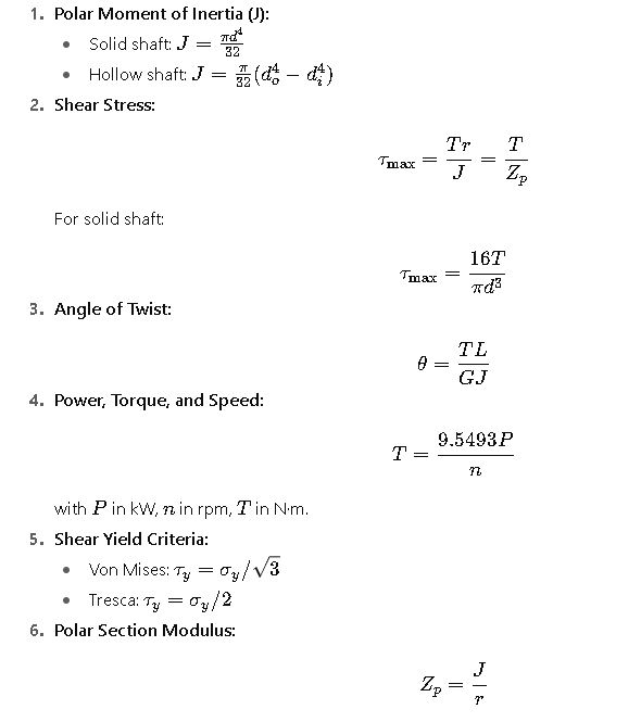
Formulas: J(solid)=π·d⁴/32 — J(hollow)=π·(D⁴−Di⁴)/32 — τ = T·r / J — θ = T·L /(G·J).
Quick Reference Tables — Common Shaft Sizes (Metric)
The following tables provide values of polar moment of inertia J, polar section modulus Zp, shear stress for a reference torque T=1000 N⋅m, and elastic twist in degrees per metre (assuming steel with shear modulus G=79 GPa).
These are highly practical for engineers who need to quickly size shafts or check preliminary designs.
Solid Circular Shafts (d = 10 mm → 200 mm, step 10 mm)
| d (mm) | d (in) | J (m⁴) | J (mm⁴) | Zp (m³) | Zp (mm³) | τ @1000 N·m (MPa) | Twist deg/m @1000 N·m |
|---|---|---|---|---|---|---|---|
| 10 | 0.394 | 9.817e-10 | 9.817e+02 | 1.963e-07 | 1.963e+02 | 5092.958 | 738.747 |
| 20 | 0.787 | 1.571e-08 | 1.571e+04 | 1.571e-06 | 1.571e+03 | 636.620 | 46.172 |
| 30 | 1.181 | 7.952e-08 | 7.952e+04 | 5.301e-06 | 5.301e+03 | 188.653 | 9.764 |
| 40 | 1.575 | 2.0106e-07 | 2.0106e+05 | 1.005e-05 | 1.005e+04 | 99.735 | 3.858 |
| 50 | 1.969 | 4.909e-07 | 4.909e+05 | 1.964e-05 | 1.964e+04 | 50.940 | 1.505 |
| 60 | 2.362 | 1.273e-06 | 1.273e+06 | 3.244e-05 | 3.244e+04 | 30.803 | 0.672 |
| 70 | 2.756 | 2.672e-06 | 2.672e+06 | 7.634e-05 | 7.634e+04 | 13.092 | 0.339 |
| 80 | 3.150 | 4.021e-06 | 4.021e+06 | 1.005e-04 | 1.005e+05 | 9.950 | 0.188 |
| 90 | 3.543 | 6.106e-06 | 6.106e+06 | 1.357e-04 | 1.357e+05 | 7.367 | 0.111 |
| 100 | 3.937 | 9.817e-06 | 9.817e+06 | 1.963e-04 | 1.963e+05 | 5.093 | 0.074 |
| 110 | 4.331 | 1.437e-05 | 1.437e+07 | 2.613e-04 | 2.613e+05 | 3.826 | 0.052 |
| 120 | 4.724 | 2.043e-05 | 2.043e+07 | 3.405e-04 | 3.405e+05 | 2.936 | 0.037 |
| 130 | 5.118 | 2.787e-05 | 2.787e+07 | 4.289e-04 | 4.289e+05 | 2.334 | 0.027 |
| 140 | 5.512 | 3.673e-05 | 3.673e+07 | 5.247e-04 | 5.247e+05 | 1.853 | 0.020 |
| 150 | 5.906 | 4.704e-05 | 4.704e+07 | 6.272e-04 | 6.272e+05 | 1.452 | 0.015 |
| 160 | 6.299 | 5.884e-05 | 5.884e+07 | 7.355e-04 | 7.355e+05 | 1.180 | 0.012 |
| 170 | 6.693 | 7.217e-05 | 7.217e+07 | 8.492e-04 | 8.492e+05 | 0.999 | 0.009 |
| 180 | 7.087 | 8.704e-05 | 8.704e+07 | 9.671e-04 | 9.671e+05 | 0.821 | 0.007 |
| 190 | 7.480 | 1.035e-04 | 1.035e+08 | 1.090e-03 | 1.090e+06 | 0.729 | 0.006 |
| 200 | 7.874 | 1.274e-04 | 1.274e+08 | 1.274e-03 | 1.274e+06 | 0.624 | 0.005 |
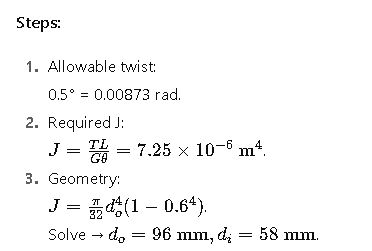
Hollow Shafts (outer diameter do, inner diameter di = 0.60·do)
| do (mm) | do (in) | di (mm) | J (m⁴) | J (mm⁴) | Zp (m³) | τ @1000 N·m (MPa) | Twist deg/m @1000 N·m |
|---|---|---|---|---|---|---|---|
| 10 | 0.394 | 6.0 | 3.230e-10 | 3.230e+02 | 6.460e-08 | 15479.197 | 2250.168 |
| 20 | 0.787 | 12.0 | 1.367e-08 | 1.367e+04 | 1.367e-06 | 731.411 | 53.047 |
| 30 | 1.181 | 18.0 | 6.922e-08 | 6.922e+04 | 4.614e-06 | 216.714 | 10.478 |
| 40 | 1.575 | 24.0 | 1.750e-07 | 1.750e+05 | 8.748e-06 | 114.275 | 4.429 |
| 50 | 1.969 | 30.0 | 4.337e-07 | 4.337e+05 | 1.734e-05 | 57.723 | 1.784 |
| 60 | 2.362 | 36.0 | 1.124e-06 | 1.124e+06 | 3.747e-05 | 26.688 | 0.799 |
| 70 | 2.756 | 42.0 | 2.283e-06 | 2.283e+06 | 6.524e-05 | 15.334 | 0.401 |
| 80 | 3.150 | 48.0 | 3.439e-06 | 3.439e+06 | 8.598e-05 | 11.628 | 0.234 |
| 90 | 3.543 | 54.0 | 5.076e-06 | 5.076e+06 | 1.128e-04 | 8.846 | 0.139 |
| 100 | 3.937 | 60.0 | 7.244e-06 | 7.244e+06 | 1.449e-04 | 6.900 | 0.092 |
| 110 | 4.331 | 66.0 | 1.014e-05 | 1.014e+07 | 1.847e-04 | 5.412 | 0.063 |
| 120 | 4.724 | 72.0 | 1.367e-05 | 1.367e+07 | 2.275e-04 | 4.396 | 0.048 |
| 130 | 5.118 | 78.0 | 1.833e-05 | 1.833e+07 | 2.821e-04 | 3.546 | 0.037 |
| 140 | 5.512 | 84.0 | 2.413e-05 | 2.413e+07 | 3.447e-04 | 2.901 | 0.029 |
| 150 | 5.906 | 90.0 | 3.107e-05 | 3.107e+07 | 4.143e-04 | 2.412 | 0.023 |
| 160 | 6.299 | 96.0 | 3.914e-05 | 3.914e+07 | 4.892e-04 | 2.020 | 0.018 |
| 170 | 6.693 | 102.0 | 4.833e-05 | 4.833e+07 | 5.669e-04 | 1.813 | 0.015 |
| 180 | 7.087 | 108.0 | 5.864e-05 | 5.864e+07 | 6.516e-04 | 1.534 | 0.012 |
| 190 | 7.480 | 114.0 | 7.007e-05 | 7.007e+07 | 7.373e-04 | 1.356 | 0.010 |
| 200 | 7.874 | 120.0 | 8.263e-05 | 8.263e+07 | 8.263e-04 | 1.210 | 0.008 |
Fundamental Formulas for Torque Calculation
Typical Values for Design
- Shear modulus GGG:
- Steel: ~79 GPa
- Aluminum: ~26 GPa
- Yield strength (σy):
- Mild steel (A36): 250 MPa
- Stainless steel (304 annealed): 205 MPa
- Alloy steels: 400–1200 MPa
- Factor of safety (FS):
- Static loading: 1.5–3
- Fatigue-critical: 2–5+
- Keyway stress concentration factor (Kt): 1.5–2.0 typical.
Worked Example 1 — Solid Shaft
Problem:
Transmit 75 kW at 1500 rpm using solid steel shaft (σy = 250 MPa). FS = 2.