Single-phase electrical systems are widely used in homes, businesses, and light industrial facilities. Accurately calculating current ensures proper design, operational safety, and system efficiency. This guide thoroughly explores single-phase current calculation, presenting detailed formulas, practical examples, and real-world applications for engineers.
Watts ↔ Amperes Calculator
Single-Phase Current Calculation: Fundamental Formula
The primary formula for calculating current in a single-phase AC circuit is derived from the relationship between power, voltage, current, and power factor:
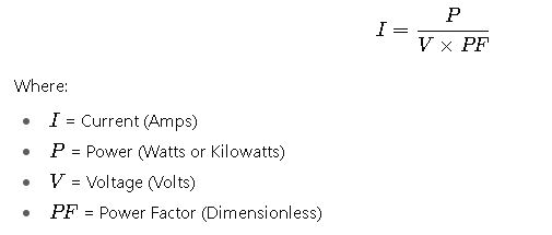
This equation assumes a sinusoidal waveform and is applicable to resistive and inductive loads.
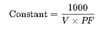
Common Constants for Single-Phase Current Calculation
To simplify calculations, constants can be used for standard voltages and power factors. These constants are derived from the formula:
| Voltage (V) | Power Factor (PF) | Constant (A/kW) |
|---|---|---|
| 120 | 1.0 | 8.33 |
| 120 | 0.9 | 9.26 |
| 230 | 1.0 | 4.35 |
| 230 | 0.9 | 4.83 |
| 240 | 1.0 | 4.17 |
| 240 | 0.9 | 4.63 |
| 277 | 1.0 | 3.61 |
| 277 | 0.9 | 4.01 |
| 415 | 1.0 | 2.41 |
| 415 | 0.9 | 2.69 |
Note: These constants are approximate and based on RMS (Root Mean Square) voltage values.
Detailed Explanation of Variables
- Power (P): The rate at which energy is consumed or produced. In AC circuits, it’s typically measured in watts (W) or kilowatts (kW). For inductive loads, real power is less than apparent power due to phase differences.
- Voltage (V): The potential difference that drives current through the circuit. In single-phase systems, common voltages include 120V, 230V, and 240V.
- Current (I): The flow of electric charge through the circuit, measured in amperes (A). It’s the quantity we aim to calculate.
- Power Factor (PF): A dimensionless number between 0 and 1 that represents the fraction of the total power that is used to do useful work. It accounts for the phase difference between voltage and current. For purely resistive loads, PF = 1; for inductive or capacitive loads, PF is less than 1.
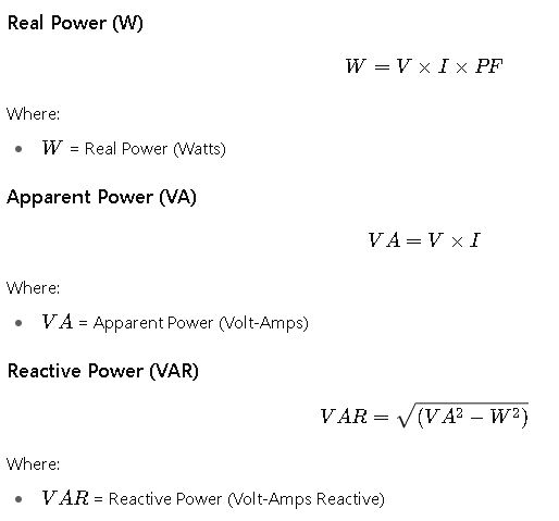
Additional Formulas for Single-Phase Circuits
Real-World Examples of Single-Phase Current Calculation
Example 1: Residential Air Conditioner
- Power: 2.5 kW
- Voltage: 230 V
- Power Factor: 0.85
Using the formula:
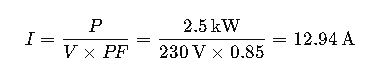
This means the air conditioner draws approximately 12.94 amperes under full load.
Example 2: Electric Water Heater
- Power: 3.6 kW
- Voltage: 240 V
- Power Factor: 1.0
Using the formula:
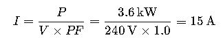
The water heater draws 15 amperes when operating at full capacity.
Practical Applications and Considerations
1. Electrical Panel Sizing
Accurate current calculations are crucial for selecting appropriately rated circuit breakers and panelboards. For instance, if a workshop has a total load of 15 kW operating at 230 V with a power factor of 0.9, the required current is:
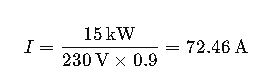
This informs the selection of a panelboard with sufficient capacity and appropriate overcurrent protection.
2. Generator Sizing
When selecting a generator, it’s essential to consider the total expected load. For a load of 10 kW at 240 V and a power factor of 0.95:
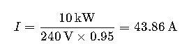
A generator rated for at least 44 amperes would be necessary to handle this load.
3. Motor Applications
Electric motors often have a power factor less than 1.0. For a motor rated at 5 kW, operating at 230 V with a power factor of 0.8:
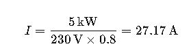
This calculation ensures that the motor is supplied with adequate current for efficient operation.
Additional Considerations
- Overcurrent Protection: Ensure that circuit breakers or fuses are rated appropriately to handle the calculated current, with consideration for inrush currents and safety margins.
- Voltage Drops: Long cable runs can cause voltage drops, affecting equipment performance. It’s essential to account for voltage drop in the design phase to ensure proper operation.
- Harmonics: Non-linear loads can introduce harmonics into the system, affecting power quality and potentially leading to overheating of conductors and equipment.
Further Reading and Resources
- EC&M: Calculating Single- and 3-Phase Parameters
- Engineering ToolBox: Single Phase Power Equations
- Electrical Technology: Power Formulas in DC and AC Single-Phase & Three-Phase Circuits