Understanding short-circuit current in cables is essential for ensuring safety, reliability, and IEC compliance.
Accurate calculations help select correct cable sizes and protective devices, preventing failures in electrical systems.
Short-Circuit Current in Cables Calculator (IEC/IEEE)
Adiabatic method — I = k · S / √t (k in A·s0.5/mm²). Materials & insulation per IEC practice.
Formulas & k constants
Typical k (A·s0.5/mm²): Cu-PVC 115, Cu-XLPE/EPR 143, Al-PVC 76, Al-XLPE/EPR 94.
Based on IEC 60364-5-54/IEC 60949 practice; for IEEE users, results are equivalent under the adiabatic assumption.
When to use adiabatic method?
What about AWG and kcmil?
Limitations & good practice
Short-Circuit Current in Cables Calculator — IEC
Fill either Source Short-Circuit Power or Source Impedance.
Format: real + j imaginary, e.g. 0.05 + j0.12
Common Reference Values for Short-Circuit Current in Cables (IEC-Based)
Below is a comprehensive table showing typical values related to cable short-circuit calculations, such as cable cross-sectional areas, conductor resistances, reactances, permissible short-circuit duration, and short-circuit current ratings according to IEC standards.
| Cable Cross-Section (mm²) | Resistance at 20°C (mΩ/m) | Reactance (mΩ/m) | Permissible Short-Circuit Duration (s) | Max Short-Circuit Current (kA) (1s) | Typical Cable Material |
|---|---|---|---|---|---|
| 1.5 | 12.1 | 0.08 | 1 | 6.0 | Copper |
| 2.5 | 7.41 | 0.07 | 1 | 9.5 | Copper |
| 4 | 4.61 | 0.06 | 1 | 12.5 | Copper |
| 6 | 3.08 | 0.05 | 1 | 16.5 | Copper |
| 10 | 1.83 | 0.04 | 1 | 24.0 | Copper |
| 16 | 1.15 | 0.03 | 1 | 31.5 | Copper |
| 25 | 0.727 | 0.02 | 1 | 40.0 | Copper |
| 35 | 0.524 | 0.02 | 1 | 48.0 | Copper |
| 50 | 0.387 | 0.015 | 1 | 55.0 | Copper |
| 70 | 0.268 | 0.012 | 1 | 65.0 | Copper |
| 95 | 0.193 | 0.010 | 1 | 75.0 | Copper |
| 120 | 0.153 | 0.009 | 1 | 80.0 | Copper |
| 150 | 0.124 | 0.008 | 1 | 85.0 | Copper |
| 185 | 0.0991 | 0.007 | 1 | 95.0 | Copper |
| 240 | 0.0755 | 0.006 | 1 | 110.0 | Copper |
Note: Values for aluminum cables will differ, typically higher resistance.
Fundamental Formulas for Short-Circuit Current Calculation in Cables (IEC Norms)
Calculating short-circuit current involves understanding cable parameters and fault conditions. Below are the critical formulas used in IEC standards, explained in detail.
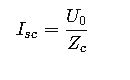
1. Short-Circuit Current (I_sc) Formula
The short-circuit current at a point in the cable can be approximated by:
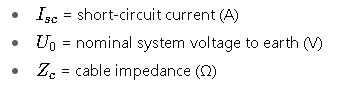
Where:
The cable impedance Zc consists of resistance and reactance components:
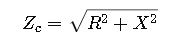
- R= resistance of the cable conductor (Ω)
- X= reactance of the cable (Ω)
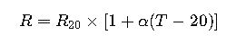
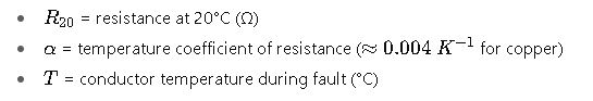
2. Resistance of the Cable at Operating Temperature
Cable resistance changes with temperature:
Where:
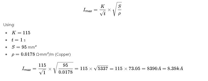
3. Maximum Permissible Short-Circuit Current (I_max)
The cable must withstand short-circuit thermal stresses without damage:
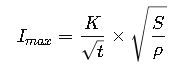
Where:
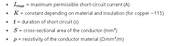
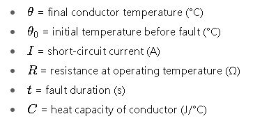
4. Temperature Rise Due to Short-Circuit
Temperature after short-circuit current flows is:
Where:
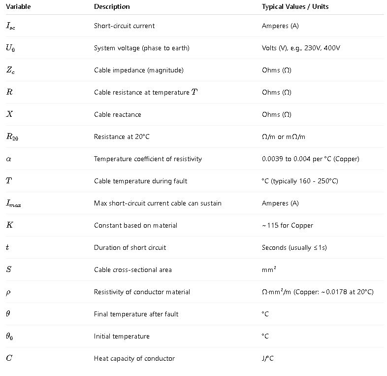
Explanation of Variables and Typical Values
IEC Standards and Guidelines Reference
- IEC 60949: Calculation of thermal endurance of electric cables under short-circuit conditions.
- IEC 60287: Calculation of continuous current rating of cables.
- IEC 60364: Electrical installations of buildings.
- IEC 60909: Short-circuit currents in three-phase AC systems.
These standards provide the framework and calculation methodologies for cable short-circuit current ratings and cable sizing.
Real-World Application Examples
Example 1: Calculating Short-Circuit Current for a 95 mm² Copper Cable in a 400 V System
Problem Statement:
Calculate the prospective short-circuit current at the end of a 50 m cable run of 95 mm² copper conductor in a 400 V, 3-phase system, assuming a fault duration of 1 second. Given:
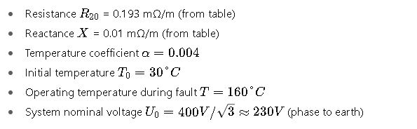
Step 1: Calculate Resistance at Operating Temperature

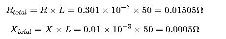
Step 2: Calculate total resistance and reactance for 50 m
Step 3: Calculate cable impedance

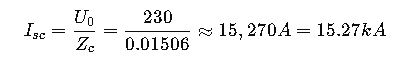
Step 4: Calculate short-circuit current
Step 5: Check maximum permissible short-circuit current
Interpretation:
The calculated prospective short-circuit current (15.27 kA) exceeds the maximum permissible cable short-circuit current (8.39 kA) for 1 second. This indicates the cable sizing or protection coordination must be adjusted to avoid cable damage during faults.
Example 2: Designing Cable for 25 mm² Aluminum Conductor in a 230 V Residential Installation
Problem Statement:
A residential building uses 25 mm² aluminum cables with a nominal voltage of 230 V single-phase. Calculate the permissible short-circuit current for a 0.5-second fault duration and determine if the cable can sustain a prospective short-circuit current of 7 kA.
Given Data:
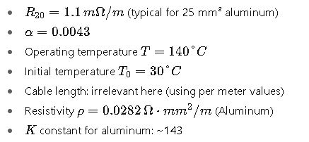
Step 1: Calculate resistance at operating temperature

Step 2: Calculate permissible short-circuit current

Interpretation:
The cable can safely withstand up to 6.02 kA for 0.5 seconds, which is below the prospective fault current of 7 kA. Therefore, either the cable size should be increased, or protective devices should operate faster or with a lower let-through current.
Additional Technical Considerations
- Cable Insulation: Short-circuit withstand capabilities depend on insulation type and thickness. IEC 60949 details these dependencies.
- Thermal Stability: Heat generated during short circuits can damage insulation if current or duration exceed design limits.
- Protective Devices Coordination: Fuse and circuit breaker ratings must coordinate with cable withstand ratings.
- Installation Conditions: Grouping, ambient temperature, and cable construction influence resistance/reactance values.
- Voltage Level: Different nominal voltages (400 V, 690 V, etc.) require adjusted calculations.
External Resources for Further Study
- IEC 60949 – IEC Webstore
- IEC 60287 – IEC Webstore
- IEEE Std 1584 Guide for Short-Circuit Calculations: IEEE Xplore
- “Electrical Power Cable Engineering” by William A. Thue (for practical engineering insights)