Compute transformer current, apply NEC factors, pick next standard OCPD; confirm 450.3 and 240.21(C) compliance.
Example (3-φ 45 kVA, 480→208/120 V): primary current ≈54 A → 125% = 68 A → select 70 A CB; secondary current ≈125 A → 125% = 156 A → select 160 A OCPD, verifying secondary-conductor protection per 240.21(C).
Primary & Secondary Protection Sizing — NEC 450.3(B) (≤1000 V)
What does NEC 450.3(B) require?
• Primary-only: max OCPD = 125% of primary current (≥9 A), 167% (2–9 A), 300% (<2 A). “Next higher” standard size is allowed only for the 125% case.
• Primary & secondary: primary OCPD up to 250% of primary current (no round-up); secondary OCPD = 125% of secondary current (≥9 A, next higher allowed) or 167% (<9 A). See Table 450.3(B).
Which standard ampere ratings does the code recognize?
Do I still have to protect secondary conductors?
Scope
Extensive Tables for Common NEC Protection Values
The following tables are based on typical transformer ratings and conductor configurations commonly used in industrial, commercial, and residential installations. All protection values are compliant with NEC Articles 240 and 450.
Table 1: Primary Overcurrent Protection (OCP) Device Ratings (600V Class Transformers – NEC 450.3(B))
| Transformer kVA | Primary Voltage (V) | Full Load Amps (FLA) | Max OCP Device Size – ≤ 600V (125%) | Max OCP Device Size – ≤ 600V (250%) |
|---|---|---|---|---|
| 3 | 480 | 3.61 | 4.5 A (round to 5 A fuse) | 9 A (round to 10 A breaker) |
| 6 | 480 | 7.22 | 9 A | 18 A |
| 15 | 480 | 18.04 | 22.55 A | 45.1 A |
| 30 | 480 | 36.08 | 45.1 A | 90.2 A |
| 45 | 480 | 54.12 | 67.6 A | 135.3 A |
| 75 | 480 | 90.2 | 112.8 A | 225.5 A |
| 112.5 | 480 | 135.3 | 169.1 A | 338.3 A |
| 150 | 480 | 180.3 | 225.4 A | 450.7 A |
Note: NEC 450.3(B) allows 250% OCP for primary-only protection (for transformers without secondary OCP).
Table 2: Secondary Overcurrent Protection Sizing – NEC 240.21(C)
| Transformer kVA | Secondary Voltage (V) | Full Load Amps (FLA) | Required OCP Device Size (125%) | Conductor Size (Cu, THWN, 75°C) |
|---|---|---|---|---|
| 15 | 208Y/120 | 41.7 | 52 A (use 60 A breaker) | #6 AWG |
| 30 | 208Y/120 | 83.4 | 104.3 A | #3 AWG |
| 45 | 208Y/120 | 125.1 | 156.4 A | 1/0 AWG |
| 75 | 208Y/120 | 208.5 | 260.6 A | 350 kcmil |
| 112.5 | 208Y/120 | 312.7 | 390.9 A | 500 kcmil |
Tip: NEC requires secondary protection within 10 ft of the transformer unless exceptions under 240.21(C) are met.
NEC-Based Formulas for Protection Sizing
Accurate sizing involves calculating the Full Load Amps (FLA) and applying NEC multipliers depending on the application and transformer protection type.
Formula 1: Full Load Amps (FLA) for Single-Phase Transformer
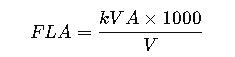
- kVA: Transformer rating in kilovolt-amperes.
- V: Voltage in volts.
- FLA: Full Load Amperes.
Formula 2: Full Load Amps (FLA) for Three-Phase Transformer
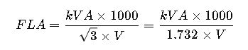
- √3 ≈ 1.732: Square root of 3 (for three-phase systems).
Formula 3: Primary Protection Sizing
When only primary protection is used (NEC 450.3(B) Table):

When both primary and secondary protection are used:

NEC allows rounding up to the next standard fuse or breaker size, except where the next size exceeds the equipment rating.
Formula 4: Secondary Protection Sizing

Use standard breaker or fuse sizes (NEC Table 240.6(A)).
Formula 5: Conductor Ampacity Check (NEC 310.16)
Ensure that:

Ampacity values are selected based on insulation type, temperature rating, and number of conductors.
Explanation of Common Variables
| Variable | Description | Typical Values |
|---|---|---|
| kVA | Transformer rating in kilovolt-amperes | 3, 6, 15, 30, 75, 112.5… |
| V | System voltage (primary or secondary) | 120, 208, 240, 480… |
| FLA | Full load current at rated kVA and voltage | Derived via formulas |
| OCP | Overcurrent protection (fuse/breaker size) | Standard per NEC 240.6(A) |
| Ampacity | Current-carrying capacity of a conductor | Per NEC 310.16 |
| % Factor | NEC protection multiplier | 125%, 250% |
Real-World Application Case Studies
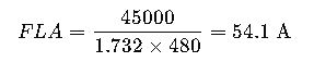
Case Study 1: Primary-Only Protection for a 45 kVA Transformer
System Specs:
- Transformer Size: 45 kVA
- Primary Voltage: 480 V (Three-Phase)
- Secondary Voltage: 208Y/120 V
- Protection Type: Primary Only
- Conductor Insulation: THWN-2, 75°C
Step-by-step Solution:
- Calculate FLA:
- Determine Maximum Primary OCP (NEC 450.3(B), up to 250% allowed):

- Check Conductor Size (Must meet ampacity ≥ 150 A):
From NEC Table 310.16, #1/0 AWG copper at 75°C = 150 A → Acceptable.
Result: Use 150 A breaker on the primary side with #1/0 Cu conductors.
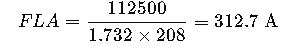
Case Study 2: Secondary Protection for a 112.5 kVA Transformer
System Specs:
- Transformer Size: 112.5 kVA
- Secondary Voltage: 208Y/120 V (Three-Phase)
- Protection Required: Secondary Only (per NEC 240.21(C)(6))
- Load Served: Distribution Panel
Solution:
- Calculate FLA:
- Determine Required OCP Size (125%):

- Conductor Sizing:
From NEC 310.16, 500 kcmil copper = 380 A → marginally less than 400 A.
Use 2 runs of 250 kcmil Cu, each rated 255 A → total ampacity = 510 A → ok
Result: Use 400 A breaker and two parallel 250 kcmil Cu conductors.
System Type Considerations: Delta vs Wye Configurations
Different system configurations affect how protection devices are applied, especially when grounding and short-circuit behavior differ.
Delta Systems
- Typically ungrounded or corner-grounded.
- Require primary protection sized carefully to detect line-to-line and line-to-ground faults.
- Secondary protection is often not mandatory for delta-delta transformers if NEC 240.21(C) exception applies.
Wye Systems
- Grounded-wye systems are more common in commercial buildings.
- Must include ground fault protection in many cases (per NEC 215.10).
- Require both primary and secondary overcurrent protection in most cases.
Special NEC Exceptions and Articles to Consider
| NEC Article | Topic / Relevance | Summary |
|---|---|---|
| 240.21(C) | Location and allowance for secondary OCP | Allows omission of secondary protection under specific conditions (e.g., ≤10 ft rule) |
| 450.3(A)(1) | Medium-voltage transformer protection (above 600V) | Primary protection required based on Table 450.3(A) |
| 240.4(B) | Next size up rule | Allows rounding up OCP rating if next standard size does not exceed conductor capacity |
| 310.16 | Ampacity tables for conductor sizing | Basis for selecting proper cable size per protection device |
| 240.6(A) | Standard fuse/breaker sizes | Reference for available protection device ratings |
Breakers vs Fuses: Which to Choose?
Choosing between breakers and fuses depends on response time, selectivity, coordination, and cost.
| Parameter | Breakers | Fuses |
|---|---|---|
| Response Time | Slower (thermal-magnetic, electronic) | Faster (especially Class J, RK1, etc.) |
| Coordination | Complex in cascaded systems | Better current-limiting capability |
| Maintenance | Resettable | Must be replaced |
| Cost | Higher initial cost | Lower upfront, but ongoing cost |
| Space Efficiency | Compact modular design | May require fuse blocks |
Use fuses for high fault current and current-limiting needs.
Use breakers where reset capability and coordination with downstream loads is essential.
Additional Tables for NEC Protection Optimization
Table 3: Standard Overcurrent Device Sizes (NEC 240.6(A))
| Amperes | Available Device Sizes |
|---|---|
| Up to 30 A | 15, 20, 25, 30 |
| 31 – 60 A | 35, 40, 45, 50, 60 |
| 61 – 100 A | 70, 80, 90, 100 |
| 101 – 225 A | 110, 125, 150, 175, 200, 225 |
| 226 – 600 A | 250, 300, 350, 400, 450, 500, 600 |
Always round up to the next standard size unless conductor ampacity is exceeded.
Table 4: Recommended Conductor Sizes for Copper (THWN, 75°C)
| OCP Size (A) | Required Conductor (Cu, 75°C) |
|---|---|
| 30 A | #10 AWG |
| 40 A | #8 AWG |
| 60 A | #6 AWG |
| 100 A | #3 AWG |
| 150 A | 1/0 AWG |
| 200 A | 3/0 AWG |
| 400 A | 500 kcmil |
| 600 A | 2 runs of 350 kcmil |
These values assume no derating due to ambient temperature or bundling. Adjust per NEC 310.15(B).
How to Use the NEC-Based Protection Calculator Effectively
An NEC calculator for primary and secondary protection must perform the following:
- Input variables:
- Transformer kVA
- Primary and secondary voltages
- System phase (single/three-phase)
- Type of protection desired (primary only, both)
- Output:
- FLA (primary and secondary)
- Recommended OCP sizes per NEC 240.6
- Recommended conductor size (based on ampacity tables)
- Dynamic logic:
- Apply NEC 450.3(B) or 450.3(A) depending on voltage class.
- Adjust for rounding using NEC 240.4(B).
- Warn user if conductor size is insufficient.
A properly implemented calculator should reference official NEC tables, apply multiplier logic, and support custom user input.
Best Practices for NEC-Compliant Protection Design
- Size protection after calculating transformer FLA, not just based on kVA tables.
- Verify conductor ampacity, especially when ambient conditions vary.
- Apply 250% for primary-only protection, but use 125% when both primary and secondary protections are used.
- Limit secondary conductor length to 10 ft unless protection is added at load end.
- Use time-current curves to ensure coordination between primary and secondary devices.
- Consult NEC Handbook or NFPA 70 for interpretation and code commentary.