Accurate panelboard sizing secures electrical distribution reliability, efficiency, and code compliance in varied installations worldwide.
This article provides a technical NEC-based calculator methodology, examples, formulas, and practical design guidance tips.
Panelboard Bus Ampacity and Main Breaker Sizing Calculator (NEC-oriented)
Scope and objectives for a Calculator Panelboard Sizing Calculator NEC approach
This document defines a robust methodology to size panelboards per the National Electrical Code (NEC), applying engineering best practices for load calculations, bus rating selection, feeder and breaker sizing, voltage drop, ambient derating, and short-circuit coordination. It targets electrical engineers, designers, and advanced technicians who require a deterministic, auditable calculator approach that can be implemented in software or manual spreadsheets.
Parameters required by the calculator
- Nominal system voltage (single-phase or three-phase).
- Load inventory with nameplate ratings (lighting, receptacles, HVAC, motors, cooking equipment, water heaters, EV chargers).
- Load type (continuous vs non-continuous, motor vs resistive vs electronic).
- Power factor for motor and non-resistive loads (typical PF values provided later).
- NEC demand factors applicable (NEC 220 series) and load grouping rules.
- Ambient temperature and conduit fill for conductor ampacity adjustments (NEC 310.15).
- Short-circuit available fault current at the point of connection (for withstand ratings and selective coordination).
- Required selective coordination and arc flash considerations (NFPA 70E, NEC 240.87 where applicable).
Stepwise calculator workflow
- Inventory: collect nameplate VA or W and categorize load types.
- Convert nameplate data to amperes using the appropriate formula for single- or three-phase systems.
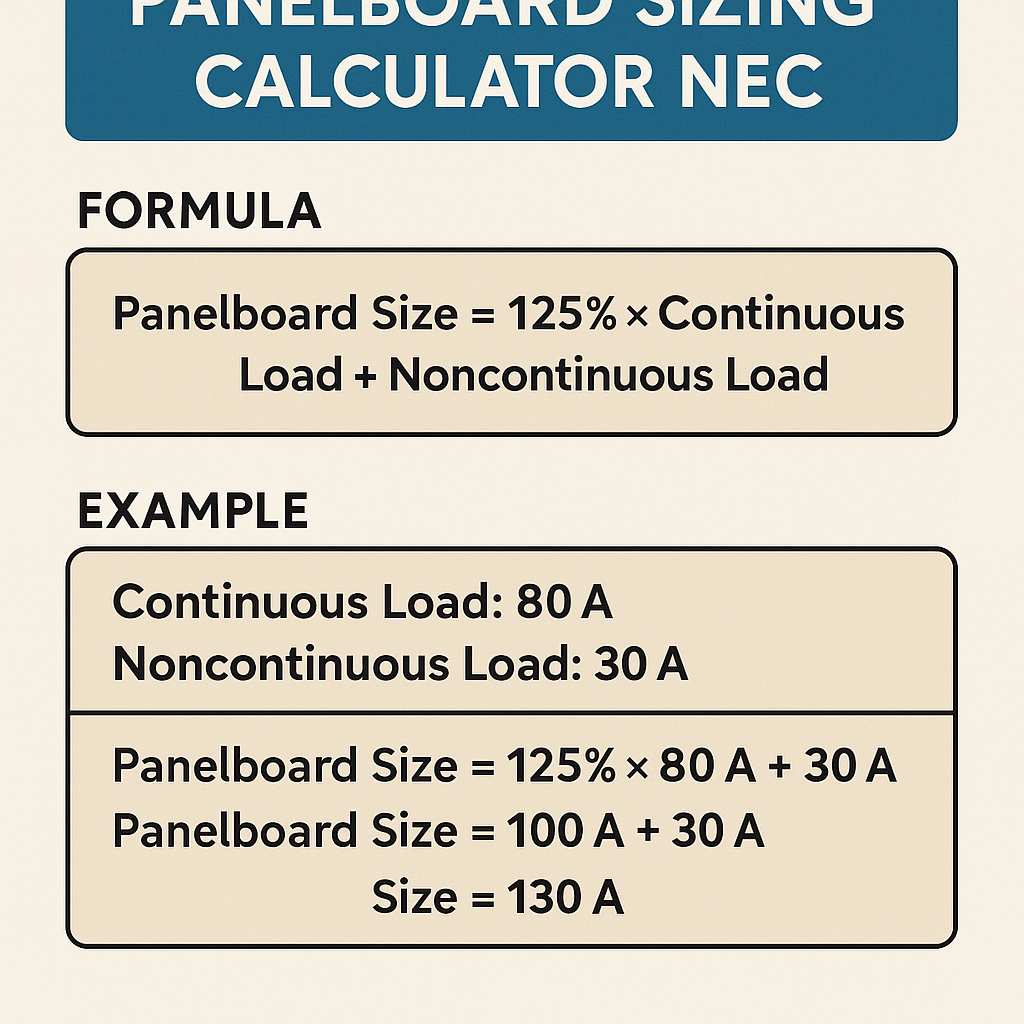
- Apply continuous load multipliers (NEC defines continuous as 3 hours or more) and sum continuous and non-continuous separately.
- Apply NEC demand factors and diversity provisions (NEC 220) based on occupancy and equipment.
- Select a bus rating ≥ calculated service or feeder current and choose main breaker rating consistent with bus and conductor ratings.
- Size conductors: select ampacity ≥ feeder current; apply temperature correction and conductor adjustment factors per NEC 310.15.
- Verify voltage drop: ensure feeder + branch circuits meet project limit (commonly ≤ 3% branch, 5% combined).
- Verify short-circuit rating and selective coordination requirements.
Essential electrical formulas (HTML text only)
Apparent power (VA): S = V * I * 1.0 for single-phase; S = V * I * 1.732 for three-phase
Voltage drop (copper conductor): Vd = I * R * L * 2 for single-phase; Vd = I * R * L * 1.732 for three-phase
Where L = one-way conductor length (feet), R = conductor resistance per foot (ohms/ft) at conductor temperature.
Explanation of variables and typical values
- I = current (amperes). Typical ranges: branch circuits 15–60 A, feeders 60–600 A or higher for commercial panels.
- P = real power (watts). Typical loads: lighting 10–50 W/fixture, small appliance circuits 1500 VA circuits, water heaters 4500 W.
- V = nominal voltage (V). Common values: 120/240 V single-phase; 208Y/120 V, 480Y/277 V three-phase.
- PF = power factor (unitless). Typical values: lighting (1.0 for resistive), motors (0.8–0.9 lagging), electronic loads (0.95–0.99 if corrected).
- R = conductor resistance (ohms/ft). Example copper #4 AWG 0.000321 ohm/ft at 75°C (use manufacturer tables).
- L = one-way length (ft). Typical lengths vary widely; use actual run length from source to panel.
NEC-oriented demand factors and common VA allocations
The calculator must implement NEC demand factors: dwelling unit general lighting (NEC 220.12), small-appliance and laundry circuits (NEC 220.52), and specialized HVAC or cooking equipment rules (NEC 220.82, 220.83). Always reference the latest NEC edition and local amendments.
| Load Category | Typical Nameplate or VA (typ) | NEC Treatment | Notes |
|---|---|---|---|
| General Lighting | 3 VA/ft² (residential typical) | Use NEC 220.12 / local code | Area-based demand factor for dwelling units and commercial spaces |
| Small-Appliance Branch Circuits | 1500 VA per circuit | NEC 220.52 | Usually 2 or more circuits for kitchens in dwellings |
| Clothes Dryer (electric) | 5000 W | NEC 220.53 | Apply specific nameplate if provided; dryers often demand-factored |
| Electric Range | 8000–12000 W | NEC 220.55 | Use table-based demand factors depending on number of ranges |
| Water Heater (resistive) | 4500 W | NEC 220.53 | Consider dedicated circuit and continuous load classification |
| Central AC (split system) | Nameplate locked-rotor and running amps used | NEC 220.82; HVAC calculations require motor rules | Include compressor locked-rotor for starting considerations |
| EV Charger (Level 2) | 3.3 kW to 19.2 kW | NEC 625 | May be continuous load; apply 125% if continuous per NEC 210.20(A) |
Panelboard bus rating and main device selection logic
Select panelboard bus rating equal to or greater than the computed continuous and non-continuous load current after demand factors. Typical bus ratings: 100 A, 125 A, 150 A, 225 A, 400 A, 600 A. Main device (breaker) must coordinate with conductors and bus rating and may be required to be the same as the bus rating or larger depending on panel manufacturer listings and UL 67 requirements.
Calculation rule-of-thumb
- If calculated feeder current ≤ 100 A, choose a 125 A bus or 125 A main breaker if space allows.
- For feeders between 100–225 A, select bus rating equal to standard increments (125, 150, 225 A).
- For larger commercial systems consider 400 A or 600 A panelboards with appropriately rated main protective devices.
Voltage drop and conductor sizing provision
Voltage drop objective should be set at design stage: commonly 3% for branch circuit or 5% combined from service to furthest load. Incorporate conductor temperature and conduit fill derating per NEC 310.15(B)(2)(a) and (C).
| Conductor Size (AWG) | Typical Ampacity (Copper THHN @75°C) | Common Breaker Size | Approx. Resistance (ohm/ft at 75°C) |
|---|---|---|---|
| 14 | 15 A | 15 A | 0.000820 |
| 12 | 20 A | 20 A | 0.000519 |
| 10 | 30 A | 30 A | 0.000326 |
| 8 | 50 A | 40–50 A | 0.000205 |
| 6 | 65 A | 60–70 A | 0.000129 |
| 4 | 95 A | 100 A | 0.000081 |
| 2 | 130 A | 150 A | 0.000051 |
Note: Use manufacturer and NEC 310.16 tables for exact ampacities and apply column selection based on conductor termination temperature rating. Values above are typical approximations for design-level calculations.
Protective device selection and coordination
Breaker and fuse selection must consider instantaneous and short-time characteristics for motor starting and selective coordination between upstream and downstream protective devices. Use time-current curves from manufacturers to verify coordination and choose proper trip curves (e.g., inverse time, short-time delay).
Coordination checklist for the calculator
- Upstream device interrupting rating ≥ available fault current.
- Downstream device clearing time less than upstream when selective coordination required.
- Arc flash boundary and PPE category determined (NFPA 70E, IEEE 1584 methodology for incident energy).
Example 1 — Residential three-bedroom single-family home panelboard sizing
Project assumptions: 3-bedroom dwelling, 2,200 ft², kitchen with electric range, dryer, water heater, central AC, two small-appliance circuits, general lighting, and heating electric baseboard absent. Service: 120/240 V single-phase.
Step 1: Load inventory (typical)
- General lighting: 3 VA/ft² × 2,200 ft² = 6,600 VA
- Small-appliance circuits: 2 × 1,500 VA = 3,000 VA
- Clothes dryer: 5,000 W (nameplate 5,000 W) = 5,000 VA
- Electric range: nameplate 8,800 W = 8,800 VA
- Water heater: 4,500 W = 4,500 VA
- Central AC: 4,000 W (running) with motor starting; use nameplate for precise values
Step 2: Apply NEC demand factors (simplified per NEC 220)
NEC 220.82 and 220.53 apply for dwelling unit calculations. Typical approach:
- General lighting and small-appliance circuits: apply 3 VA/ft² already used for lighting; small-appliance circuits are counted at 1,500 VA each (NEC allows diversity via 220.82).
- Apply demand factor for ranges based on Table 220.55. For a single range at 8,800 W, the demand allows the table value (use 8,800 nameplate without multiplier if single).
Step 3: Compute load (simplified)
Convert to amperes at 240 V single-phase: I = P / V = 31,900 VA / 240 V = 132.9 A
Step 4: Apply continuous load factor and service sizing
If any loads are continuous (water heater is often not continuous; central AC cyclical), assume 125% of continuous portion when sizing conductors and overcurrent devices per NEC 210.20(A) and 215.3. If 20% of total load is continuous, continuous portion = 6,380 VA → current = 26.6 A increased to 125% for device sizing.
Step 5: Select panelboard and main breaker
Calculated load ≈ 133 A. Selecting a 200 A service is common for future expansion and to meet code allowances; however, a 150 A service might be acceptable if local code and load calculations permit. For conservative design and allowance for future EV charger addition, choose 200 A, 120/240 V main breaker and 200 A rated panelboard bus.
Step 6: Conductor sizing and voltage drop check
For a 200 A feeder, typical conductor is copper 3/0 AWG or aluminum 300 kcmil depending on ampacity and termination rating. Check voltage drop for furthest branch; ensure combined feeder and branch <5%.
Solution summary
- Calculated load: 132.9 A (31.9 kVA)
- Recommended service: 200 A, 120/240 V main breaker and panelboard
- Feeder conductor: copper 3/0 AWG (verify ampacity & termination temperature)
- Voltage drop: verify using length; adjust conductor gauge if necessary
Example 2 — Small commercial office panelboard sizing (three-phase)
Project assumptions: 10,000 ft² office, 208Y/120 V three-phase, LED lighting, receptacle loads, server room UPS (kVA), HVAC rooftop unit, and small kitchenette appliances.
Step 1: Load inventory
- Lighting: 1.5 W/ft² × 10,000 ft² = 15,000 W (15,000 VA)
- Receptacle/outlets: 3 VA/ft² × 10,000 ft² = 30,000 VA
- Rooftop HVAC unit: 15 kW (15,000 W), motor starting considerations
- Server room UPS: 30 kVA (30,000 VA) at 0.9 PF (real load = 27,000 W)
- Kitchenette: microwave and refrigerator combined 3 kW
Step 2: Convert and sum three-phase currents
Compute three-phase current using PF where applicable (use conservative PF = 0.95 overall): I = P / (V * PF * 1.732) = 90,000 / (208 * 0.95 * 1.732)
Current I ≈ 90,000 / 342.9 ≈ 262.6 A
Step 3: Demand factors and diversity
Apply diversity: lighting and general receptacle may have demand reductions. For preliminary sizing, apply 65% demand factor to general receptacle and 100% lighting (conservative) or per local code. For the UPS and HVAC, use nameplate loads; treat UPS as continuous (apply 125% per code when sizing overcurrent devices).
Step 4: Adjust for continuous loads and sizing
Assume continuous portion 30 kW (including UPS critical loads). Apply 125% for overcurrent device sizing. Adjusted feeder current becomes larger accordingly: continuous current portion in amperes and add non-continuous currents.
Step 5: Select panelboard and main device
Computed current ≈ 263 A; choose a 400 A three-phase panelboard or two 225 A feeders with distribution depending on service configuration. Many designers choose 400 A bus with a 400 A main breaker to provide expansion and coordination flexibility.
Step 6: Conductor sizing and selective coordination
- For 400 A feeder, copper 600 kcmil or aluminum 750 kcmil may be required – use NEC tables and conductor insulation types.
- Coordinate HVAC motor overloads with upstream protective devices and ensure short-circuit current rating of panel and breakers exceeds available fault current.
Solution summary
- Calculated three-phase load current ~263 A
- Recommended panelboard: 400 A, 208Y/120 V three-phase bus
- Feeder conductor: sized per NEC ampacity and voltage drop (consult 310.16)
- Verify selective coordination and arc flash mitigation per NFPA 70E
Implementation hints for a calculator UI and UX
- Inputs: allow import of nameplate data, selection of occupancy type, square footage, and automatic application of NEC demand tables.
- Provide clear flags for continuous loads, motor loads, and unbalanced phase loading.
- Offer iterative outputs: summary currents, recommended panelboard rating options, conductor sizes, expected voltage drop, and short-circuit rating checks.
- Exportable calculation report with references to NEC clauses and manufacturer datasheets for auditability.
Regulatory references and industry standards
Always cross-check calculator outputs against the latest code editions and product listings. Key references:
- NFPA 70 — National Electrical Code (NEC): https://www.nfpa.org/nec
- NFPA 70E — Standard for Electrical Safety in the Workplace (arc flash and PPE): https://www.nfpa.org/70E
- UL 67 — Standard for Panelboards: https://www.ul.com
- IEEE 1584 — Guide for arc-flash hazard calculations: https://standards.ieee.org/standard/1584-2018.html
- NEMA — Panelboard and switchgear publications: https://www.nema.org
- Manufacturer data sheets for breakers, panelboards, and conductors (e.g., Eaton, Square D by Schneider Electric, Siemens).
Best-practice checklist for final verification
- Confirm all nameplate data matches installed equipment.
- Verify load diversity and application of the correct NEC sections.
- Ensure conductor ampacity meets corrected temperature and adjustment factors per NEC 310.15(B)(2)(a) and (B)(3).
- Validate voltage drop to acceptable limits and increase conductor size if necessary.
- Verify panelboard and breaker short-circuit interrupting rating ≥ available fault current.
- Confirm selective coordination where required and document time-current curve evaluations.
- Document arc flash incident energy study outcomes and PPE requirements.
- Keep records of calculations for permitting and future audits.
Common pitfalls and mitigation strategies
- Underestimating continuous loads — mitigation: conservative identification and 125% multiplier when applicable.
- Neglecting diversity rules — mitigation: automate NEC table application but allow engineer override.
- Ignoring ambient temperature derating — mitigation: request site ambient profile and conduit grouping data.
- Mismatch between panel listing and breaker selection — mitigation: use manufacturer compatibility matrices and UL listings.
- Failing to account for future loads (EV charging, expansion) — mitigation: design for plausible growth or modular expansion.
Performance validation and testing
Post-installation testing is critical. Perform the following:
- Insulation resistance testing (megger) on feeders and branch circuits.
- Verification of phase rotation and voltage balance.
- Operational trip testing of overcurrent protective devices under simulated loads where safe and feasible.
- Coordination testing using test equipment or simulation of fault clearing times based on manufacturer time-current curves.
Appendix — Additional table: Typical motor nameplate considerations
| Motor HP | Typical Full Load Amps (FLA) at 480V 3Ø | Typical FLA at 208V 3Ø | Starting considerations |
|---|---|---|---|
| 1 HP | 1.6 A | 4.0 A | Minimal inrush; soft-start often unnecessary |
| 5 HP | 6.9 A | 17.4 A | Moderate inrush; consider service rating |
| 10 HP | 13.0 A | 34.8 A | Significant inrush; consider reduced-voltage starter |
| 25 HP | 30.0 A | 80.0 A | High inrush; protective coordination essential |
| 50 HP | 60.0 A | 160.0 A | Require motor starters and upstream protective device coordination |
Final engineering notes
Implementing a reliable panelboard sizing calculator requires careful translation of NEC rules into deterministic algorithms with override options for engineer judgment. Track assumptions, include safety margins, and always cite code clauses in the delivered calculation report so authorities and inspectors can approve installations confidently.
Further reading and authoritative resources
- NEC Handbook explanation chapters (NFPA): provides commentary and worked examples for 220 series calculations.
- IEEE 1584 for arc flash incident energy assessment and mitigation planning.
- Manufacturer’s panelboard and breaker catalogs for compatibility and listing data (Eaton, Schneider Electric, Siemens).