Understanding line impedance is crucial for designing, analyzing, and operating power transmission and distribution systems efficiently.
Accurate calculations reduce system losses, enhance reliability, and enable precise relay coordination and effective fault protection.
Line Impedance Calculator (R, X & |Z|) — with Conductor & Standard Presets
Optional: Voltage Drop
What does this calculator do?
Formulas used
R = R′ × L / n, X = X′ × L / n, |Z| = √(R²+X²), ∠Z = atan(X/R).Temperature:
R(T) = R(20 °C) × [1 + α × (T − 20)] (Cu≈0.00393/°C, Al≈0.00403/°C).Loop/L–L path (typical):
Z_loop ≈ 2 × Z_one-way.Voltage drop (approx): 1Φ
ΔV% ≈ 100 × I × (R·cosφ + X·sinφ) / V; 3Φ ΔV% ≈ 100 × √3 × I × (R·cosφ + X·sinφ) / V_LL.How are presets built?
Extensive Reference Tables for Line Impedance Parameters (IEEE & IEC)
Line impedance consists of resistance (R), inductive reactance (X), and sometimes capacitive reactance (C) components, but typically R and X dominate for overhead and underground lines. The values vary according to conductor type, size, spacing, and configuration.
The tables below show common conductor sizes and their typical per-unit-length impedances based on IEEE and IEC standards. These values are essential inputs for any line impedance calculator.
| Conductor Type | Cross-Section (mm²) | Resistance @ 20°C (Ω/km) | Inductive Reactance (X) (Ω/km) | Positive Sequence Impedance (Z₁) (Ω/km) | Zero Sequence Impedance (Z₀) (Ω/km) | Standard Reference |
|---|---|---|---|---|---|---|
| ACSR (Aluminum Conductor Steel Reinforced) 636.8 kcmil (322 mm²) | 322 | 0.060 | 0.35 | 0.36 + j0.35 | 0.58 + j0.12 | IEEE Std 141-1993 |
| Copper 250 kcmil (127 mm²) | 127 | 0.082 | 0.34 | 0.36 + j0.34 | 0.55 + j0.10 | IEC 60287-1 |
| Aluminum 477 kcmil (242 mm²) | 242 | 0.077 | 0.32 | 0.33 + j0.32 | 0.51 + j0.09 | IEEE Std 738-2012 |
| Copper 500 MCM (253 mm²) | 253 | 0.066 | 0.31 | 0.34 + j0.31 | 0.52 + j0.08 | IEEE Std 399-1997 |
| Aluminum 795 kcmil (403 mm²) | 403 | 0.048 | 0.30 | 0.31 + j0.30 | 0.47 + j0.07 | IEC 60853-2 |
Additional Line Constants
| Parameter | Typical Range | Unit | Notes |
|---|---|---|---|
| Line Length (L) | 1 – 300 | km | Depends on power system configuration |
| Frequency (f) | 50 / 60 | Hz | Standard power system frequency |
| Earth Resistivity (ρ) | 10 – 1000 | Ω·m | Influences zero-sequence impedance |
| Conductor Spacing (D) | 0.3 – 1.5 | m | Affects mutual inductance and capacitance |
Core Formulas for Line Impedance Calculation (IEEE & IEC)
Calculating the impedance of overhead or underground lines requires applying the fundamental principles of electromagnetic theory, represented by the following formulas:
1. Conductor Resistance (R)
Resistance per unit length varies with conductor material, temperature, and cross-sectional area.
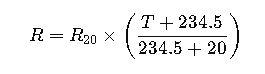
- R: Resistance at operating temperature T (°C) (Ω/km)
- R20: Resistance at 20°C (Ω/km)
- T: Operating conductor temperature (°C)
Explanation: Resistance increases with temperature due to increased electron scattering in the conductor.
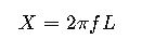
2. Inductive Reactance (X)
The inductive reactance per unit length can be computed as:
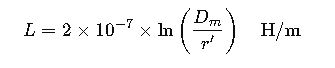
Where the inductance per unit length L is estimated using the Geometric Mean Distance (GMD) and Geometric Mean Radius (GMR):
- f: Frequency (Hz)
- Dm: Geometric Mean Distance between conductors (m)
- r′: Equivalent conductor radius, accounting for skin effect and bundling (m)
Note: IEEE and IEC define r′ differently based on conductor configuration.
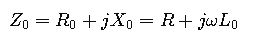
3. Positive Sequence Impedance (Z₁)
Represents the impedance in balanced three-phase operation:

Where R and X are resistance and inductive reactance per unit length.
4. Zero Sequence Impedance (Z₀)
In unbalanced conditions, zero sequence impedance must be evaluated:
L0 accounts for earth return path effects and is calculated as:
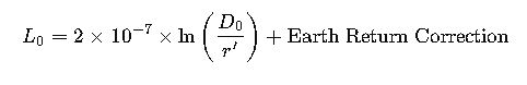
Where:
- D0: Equivalent zero-sequence GMD
- Earth return correction depends on soil resistivity (IEEE Std 142 / IEC 60909 references)
5. Impedance of Overhead Lines
Using Carson’s equations (IEEE Std 80-2013, IEC 60909):
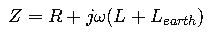
Where LearthL_{earth}Learth accounts for earth return path inductance, calculated from soil resistivity and conductor height.
6. Impedance of Underground Cables
IEC 60287-1-1 specifies cable impedance calculation, incorporating:
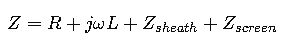
 Impedances from cable sheath and screens, critical for high-voltage cables.
Explanation of Variables and Typical Values

Real-World Examples of Line Impedance Calculation (IEEE & IEC)
Case Study 1: Overhead Transmission Line Impedance Calculation
System Description:
- 138 kV, three-phase overhead line
- Conductors: ACSR, 636.8 kcmil (322 mm²)
- Span length: 50 km
- Conductor spacing: 1.2 m phase-to-phase
- Operating temperature: 75°C
- Frequency: 60 Hz
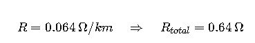
Step 1: Calculate Resistance at Operating Temperature
Given:
- R20=0.060 Ω/km
- T=75°C

Step 2: Calculate Inductive Reactance
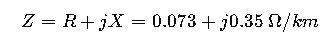
Using the inductive reactance typical value for this conductor X=0.35 Ω/km
Step 3: Calculate Total Impedance per km
Step 4: Calculate Total Line Impedance
For L=50 km
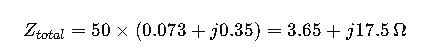
This value is essential for fault analysis and relay coordination.
Case Study 2: Underground Cable Line Impedance Calculation (IEC)
System Description:
- 33 kV, three-core XLPE cable
- Cable cross-section: 300 mm² copper
- Length: 10 km
- Frequency: 50 Hz
- Soil resistivity: 100 Ω·m
Step 1: Determine Resistance
From IEC 60287:
Step 2: Calculate Inductive Reactance
Using cable data and GMD for three-core:
torsconversion.com/wp-content/uploads/2025/04/i-847.jpg" alt="" class="wp-image-46644"/>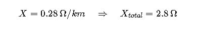 Publicidad