Lightning protection is essential for building safety and electrical infrastructure against dangerous lightning strikes. Calculating the required Lightning Protection Level (LPL) per NFPA 780 and IEC 62305 standards protects structures.
Lightning Protection Level Calculator – NFPA 780 / IEC 62305
Extensive Tables of Common Values for Lightning Protection Levels (NFPA 780 & IEC 62305)
The Lightning Protection Level is categorized based on several parameters: Protection Level (PL), Lightning Current Parameters, Air Terminals, Down Conductors, Separation Distance, and Surge Protective Devices (SPDs).
Below are detailed tables covering common values according to NFPA 780 and IEC 62305.
Table 1: Lightning Protection Levels and Corresponding Parameters (IEC 62305)
| Protection Level | Maximum Lightning Current (I_peak, kA) | Charge Transfer (Q, C) | Specific Energy (J/kg) | Equivalent Lightning Current (kA) | Typical Applications |
|---|---|---|---|---|---|
| Level I | 200 | 500 | 1.0 × 10^7 | 200 | High-risk facilities (airports, tall buildings) |
| Level II | 150 | 370 | 6.25 × 10^6 | 150 | Medium-risk industrial buildings |
| Level III | 100 | 250 | 2.5 × 10^6 | 100 | Residential and commercial buildings |
| Level IV | 50 | 125 | 1.0 × 10^6 | 50 | Low-risk residential and small buildings |
Table 2: Lightning Protection Level Parameters According to NFPA 780
| Lightning Protection Level | Peak Current (I_peak, kA) | Number of Lightning Strikes per Year | Minimum Air Terminal Height (m) | Typical Installation Scope |
|---|---|---|---|---|
| Level 1 | 200 | 10 | ≥ 3 | Critical facilities (hospitals, communication towers) |
| Level 2 | 150 | 5 | ≥ 2 | Industrial plants, warehouses |
| Level 3 | 100 | 2 | ≥ 1 | Commercial buildings |
| Level 4 | 50 | 1 | ≥ 0.5 | Residential homes |
Table 3: Surge Protective Device (SPD) Voltage Protection Level (VPL) According to LPL
| Protection Level | Maximum Discharge Current (kA) | Voltage Protection Level (VPL, kV) | Recommended SPD Class (IEC 61643-11) |
|---|---|---|---|
| Level I | 200 | ≤ 6 | Class I |
| Level II | 150 | ≤ 4 | Class I/II |
| Level III | 100 | ≤ 2.5 | Class II/III |
| Level IV | 50 | ≤ 1.5 | Class III |
Table 4: Typical Dimensions and Spacing for Air Terminals and Conductors (NFPA 780)
| Parameter | Level 1 | Level 2 | Level 3 | Level 4 |
|---|---|---|---|---|
| Air Terminal Spacing (m) | 3 | 4 | 5 | 6 |
| Down Conductor Diameter (mm) | 10 | 8 | 6 | 5 |
| Separation Distance (mm) | ≥ 100 | ≥ 75 | ≥ 50 | ≥ 30 |
| Conductor Material | Copper/Aluminum | Copper/Aluminum | Copper/Aluminum | Copper/Aluminum |
Formulas for Lightning Protection Level Calculation – NFPA 780 & IEC 62305
Lightning Protection Level calculations involve determining parameters such as the equivalent lightning current, charge transfer, specific energy, and separation distances between conductors and sensitive parts of the structure.
Below are the fundamental formulas, their explanations, and commonly used values.
1. Peak Lightning Current (I_peak)
The Peak Lightning Current is the maximum current magnitude during a lightning strike, measured in kiloamperes (kA). This value varies based on the protection level:

Typical values range from 50 kA (LPL IV) to 200 kA (LPL I).
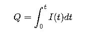
2. Charge Transfer (Q)
Charge Transfer (Q) represents the total electric charge transferred during the lightning strike, measured in coulombs (C).
For simplified calculations, the standard charge values per protection level are:
| LPL | Q (Coulombs) |
|---|---|
| I | 500 |
| II | 370 |
| III | 250 |
| IV | 125 |
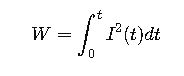
3. Specific Energy (W/mass or J/kg)
Specific Energy represents the energy density that the lightning strike delivers, related to the thermal and mechanical stresses in the structure and equipment.
In practical terms:
| LPL | Specific Energy (J/kg) |
|---|---|
| I | 1.0 \times 10^{7} |
| II | 6.25 \times 10^{6} |
| III | 2.5 \times 10^{6} |
| IV | 1.0 \times 10^{6} |
4. Equivalent Lightning Current (I_eq)
IEC 62305 defines an equivalent lightning current for design purposes, considering the peak current and the waveform:
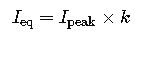
Where:
- k is a factor considering the waveform shape (typically k≈0.9k≈0.9 for 10/350 µs waveform).
5. Minimum Separation Distance (S)
Separation distance is critical to prevent flashover or arcing between the lightning protection system and the structure or internal electrical systems.
According to IEC 62305-3, the minimum separation distance S can be calculated as:
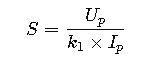
Where:
- S= Minimum separation distance (meters)
- Up= Protective level voltage (kV)
- k1= Constant depending on insulation type (kV/kA)
- Ip= Lightning impulse current (kA)
Typical values:
| Insulation Type | k1k_1k1 (kV/kA) |
|---|---|
| Solid insulation | 20 |
| Air insulation | 25 |
6. Voltage Protection Level (VPL) for SPDs
To ensure proper protection of electrical equipment, Surge Protective Devices must have a voltage protection level below the insulation withstand voltage.
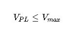
Where:
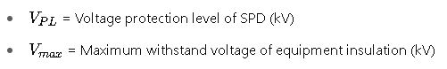
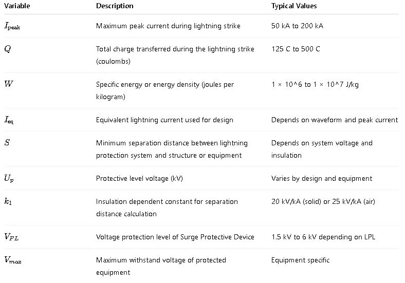
Explanation of Variables
Real-World Application Examples
Case 1: Lightning Protection Design for a 50m Tall Commercial Building (Level II Protection)
Scenario:
A 50-meter tall commercial building located in an area with moderate lightning activity requires Level II protection as per NFPA 780 and IEC 62305.
Given Data:
| Parameter | Value |
|---|---|
| Building height | 50 m |
| Protection Level | Level II |
| Peak Lightning Current (Ipeak) | 150 kA |
| Charge Transfer (Q) | 370 C |
| Specific Energy (W) | 6.25 × 10^6 J/kg |
| Minimum Air Terminal Height | ≥ 2 m |
| Down Conductor Diameter | 8 mm |
Calculation Steps:
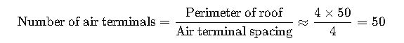
1.Determine the number and spacing of air terminals: Using NFPA 780 guidance, air terminals are spaced approximately every 4 meters for Level II.
2.Calculate minimum separation distance:
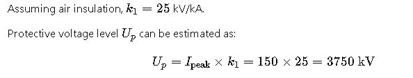
However, this is excessive and needs correction based on practical SPD and insulation ratings. More typical voltage protection levels for Level II are around 4 kV (from Table 3).
- Surge Protective Device selection: According to Table 3, SPD Class I/II is recommended with a voltage protection level ≤ 4 kV.
Case 2: Lightning Protection for a Small Residential House (Level IV Protection)
Scenario:
A single-family house requires Level IV protection per IEC 62305 with low risk and typical lightning activity.
Given Data:
| Parameter | Value |
|---|---|
| Building height | 7 m |
| Protection Level | Level IV |
| Peak Lightning Current (Ipeak) | 50 kA |
| Charge Transfer (Q) | 125 C |
| Specific Energy (W) | 1 × 10^6 J/kg |
| Air Terminal Spacing | 6 m |
Calculation Steps:
1.Air terminal placement: For small residential buildings, air termina
ls are spaced about 6 m apart.2.Down conductor sizing: According to Table 4, down conductor diameter for Level IV can be 5 mm copper or aluminum.
3.Separation distance: This very small distance indicates low risk for flashover within the structure; standard wiring practices are sufficient.
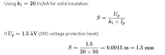
4.SPD Selection: A Class III SPD with a voltage protection level ≤ 1.5 kV is recommended.
Additional Technical Considerations
- Waveform Selection: IEC 62305 typically uses a 10/350 µs waveform for lightning current, representing the steep front and slow tail of actual lightning current.
- Earthing Systems: The grounding system must be designed to handle the lightning current with minimal resistance to prevent side-flashes and ensure proper current dissipation.
- Bonding and Equipotentialization: All metallic parts and conductive systems must be bonded to avoid potential differences during lightning strikes.
- Surge Protection Coordination: SPD selection must coordinate with insulation withstand voltages and system grounding to avoid nuisance trips or failures.
Authoritative External References
- NFPA 780: https://www.nfpa.org/codes-and-standards/all-codes-and-standards/list-of-codes-and-standards/detail?code=780
- IEC 62305 Standard Overview: https://webstore.iec.ch/publication/2453
- IEEE Guide for Surge Protection: https://ieeexplore.ieee.org/document/1412259
- Lightning Protection Institute (LPI): https://lightning.org