Lightning protection systems safeguard electrical installations, industrial facilities, and infrastructures against surges, overvoltages, and lightning strikes. International standards NFPA 780 and IEC 62305 provide guidelines for selecting lightning arresters and surge devices.
Lightning Arrester & Surge Protection Selection Calculator
Quick recommendations (Type 1 / Type 2 / Type 3) and suggested discharge currents based on NFPA 780, IEC 62305 and IEC 61643 guidance.
Why Type 1 / Type 2 / Type 3?
What is “nominal discharge current” (In) and “impulse current” (Iimp)?
Formulas / logic used
- If external LPS present → Type 1 or Type 1+2 at service entrance (high impulse capability).
- Critical sites & sensitive equipment → Stage protection: Type 1+2 at service, Type 2 at distributions, Type 3 at sensitive terminals.
- Typical installations without LPS → Type 2 (main distribution) + Type 3 for sensitive loads.
Importance of Correct Lightning Arrester and Surge Protection Selection
- Prevents catastrophic equipment damage caused by transient surges.
- Ensures compliance with safety regulations and insurance requirements.
- Extends the service life of sensitive electronic and electrical devices.
- Provides protection for human life in residential, industrial, and critical infrastructure environments.
Standards Framework: NFPA 780 vs. IEC 62305
| Aspect | NFPA 780 | IEC 62305 |
|---|---|---|
| Scope | U.S.-focused installation requirements for lightning protection | Global methodology for risk assessment, LPS design, and surge protection |
| Focus | Structural lightning protection and grounding | Comprehensive: risk management, protection levels (LPL I–IV), SPDs |
| SPD Integration | References UL 1449 for surge protection devices | Defines SPD categories (Type 1, 2, 3) and energy withstand levels |
| Risk Assessment | Simplified | Detailed probabilistic assessment model |
| Applicability | Buildings, industrial plants, hazardous sites | Broader: telecoms, IT, power systems, structures, services |
Both standards converge on the principle that lightning arresters and SPDs must be selected based on:
- Lightning protection level (LPL).
- System voltage and insulation level.
- Impulse withstand requirements.
- Grounding resistance.
Key Formulas for Lightning Arrester and SPD Selection
1. Peak Lightning Current (IEC 62305)
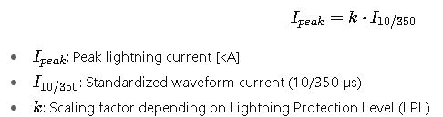
| LPL | Current (I10/350 µs) | Probability of Exceedance |
|---|---|---|
| I | 200 kA | 2% |
| II | 150 kA | 5% |
| III | 100 kA | 10% |
| IV | 100 kA | 20% |
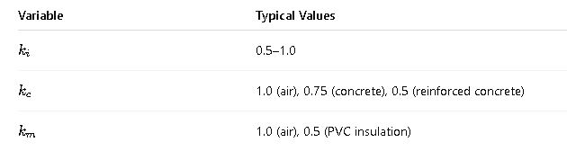
2. Separation Distance (NFPA 780 / IEC 62305)
To prevent dangerous flashover between conductive parts:
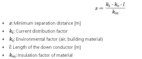
Common values:
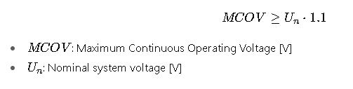
3. Surge Protective Device (SPD) Selection
The maximum continuous operating voltage (MCOV) of an SPD must be greater than the system’s nominal RMS voltage:
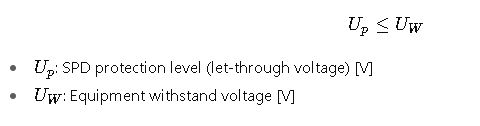
4. Protection Level Coordination (IEC 62305-4)
The SPD’s protection level must be below the withstand level of the protected equipment:
5. Grounding Resistance Requirement (NFPA 780)
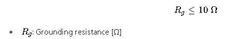
For sensitive facilities (data centers, hospitals), recommended ≤ 5 Ω.
Extended Reference Tables for Common Values
Table 1. Typical SPD Ratings (IEC / UL 1449)
| SPD Type | Location of Use | Test Waveform | Nominal Discharge Current InI_nIn | Impulse Current IimpI_{imp}Iimp |
|---|---|---|---|---|
| Type 1 | Service entrance | 10/350 µs | 20–25 kA | 50–100 kA |
| Type 2 | Distribution boards | 8/20 µs | 5–20 kA | 40–80 kA |
| Type 3 | Local equipment protection | Combination (1.2/50 – 8/20 µs) | 1–5 kA | 10–20 kA |
Table 2. Typical MCOV Values for Different Systems
| System Voltage (Nominal) | MCOV Range (V) | SPD Class Recommendation |
|---|---|---|
| 120/240 V (single-phase) | 150–320 V | Type 1 or 2 |
| 208/120 V (3-phase wye) | 150–320 V | Type 2 |
| 480/277 V (3-phase wye) | 320–640 V | Type 1 or 2 |
| 600 V delta | 550–800 V | Type 1 |
Table 3. Lightning Density by Geographic Region (IEC 62305-2 Reference)
| Region | Ground Flash Density NgN_gNg (flashes/km²/year) |
|---|---|
| Central Africa | 40–60 |
| South America (Amazon) | 20–40 |
| Southeast Asia | 15–25 |
| North America | 5–15 |
| Europe | 2–10 |
| Northern Latitudes | <2 |
These values strongly influence risk assessment calculations and SPD sizing.
Real-World Example 1: Industrial Plant Protection
Scenario:
- Location: Southeast Asia (Ng = 20 flashes/km²/year)
- Facility: 480/277 V industrial plant, multiple VFDs and PLCs
- Standards applied: IEC 62305, NFPA 780
Steps:
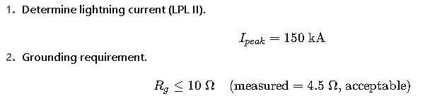
3.SPD selection.
- Nominal voltage: 480/277 V → choose MCOV ≥ 320–640 V.
- Type 1 SPD installed at service entrance: 50 kA, 10/350 µs.
- Type 2 SPD installed at distribution panels: 20 kA, 8/20 µs.
4.Coordination check.
- Equipment withstand voltage: 2.5 kV.
- SPD protection level Up=1.5 kV
- Within limits.
5.Final system design:
- Type 1 + Type 2 SPDs coordinated.
- Supplementary Type 3 SPDs for PLC cabinets.
Real-World Example 2: Data Center Protection
Scenario:
- Location: North America, lightning density of 8 flashes/km²/year.
- Facility: Tier IV Data Center with redundant 208/120 V power supply.
- Standards applied: NFPA 780, IEC 62305-4.
Steps:
- Lightning Risk Assessment
The moderate lightning density combined with critical equipment sensitivity results in a high-risk profile. Data centers cannot tolerate downtime; therefore, the protection system must be designed with redundancy. - Grounding and Bonding
Grounding electrodes are interconnected in a mesh arrangement, achieving a resistance of 3 Ω, well below the recommended threshold for sensitive installations. This ensures proper dissipation of surge energy and minimizes potential differences within the site. - Surge Protection Device Placement
- Service entrance: Type 1 SPDs capable of withstanding high-energy lightning currents.
- Distribution boards: Type 2 SPDs to suppress switching surges and residual lightning energy.
- Server racks: Type 3 SPDs installed in rack-mounted power distribution units (PDUs) to protect individual IT hardware.
- Coordination of Protection Levels
Equipment installed in data centers typically has an impulse withstand level of around 1.5 kV. SPDs were chosen with protection levels of less than 1.2 kV, guaranteeing compliance with IEC 62305-4 coordination requirements. - Final Outcome
After implementation, the data center achieved full compliance with both NFPA 780 and IEC 62305. The system ensures uninterrupted operation even during seasonal thunderstorms, protecting multimillion-dollar IT infrastructure and maintaining Service Level Agreements (SLAs).
Key Considerations When Selecting Lightning Arresters and SPDs
- Lightning Density of the Region: The higher the ground flash density, the more robust the protection must be.
- Lightning Protection Level (LPL): Defines the maximum current a system must withstand. LPL I is the most stringent, requiri ng higher-rated devices.
- Nominal System Voltage: Determines the maximum continuous operating voltage (MCOV) required for SPDs.
- Withstand Level of Equipment: The SPD’s protection level must always be below the dielectric strength of the connected equipment.
- Grounding Resistance: Lower resistance values improve dissipation of surge energy and reduce residual overvoltages.
- Installation Location: SPDs must be installed in layers (cascaded protection) — service entrance, distribution panels, and final load.
- Coordination of Devices: Proper coordination ensures that SPDs operate in sequence, preventing overload of downstream devices.
Extended SPD Selection Guide
Table 4. Recommended SPD Applications by Installation Level
| Installation Level | Typical Device | Current Capacity | Function |
|---|---|---|---|
| Service entrance | Type 1 SPD | High-energy (50–100 kA) | Handles direct lightning currents |
| Main distribution board | Type 2 SPD | Medium-energy (20–40 kA) | Handles switching surges and residual energy |
| Sensitive equipment | Type 3 SPD | Low-energy (5–10 kA) | Provides fine protection for electronics |
Table 5. Equipment Withstand Levels (IEC Reference Values)
| Equipment Type | Typical Withstand Level | Notes |
|---|---|---|
| Industrial motors | 4–6 kV | Higher tolerance due to robust insulation |
| PLCs and control systems | 2.5 kV | Requires intermediate protection |
| Data servers | 1.5 kV | Very sensitive, needs Type 3 SPD |
| Telecom equipment | 1–1.5 kV | Extremely sensitive, often requires hybrid SPD |
Risk Management Perspective
Both NFPA 780 and IEC 62305 emphasize that protection is not just a matter of device selection, but a holistic system approach. Proper implementation includes:
- Lightning rods and down conductors for physical interception.
- Equipotential bonding to avoid dangerous voltage differences.
- Grounding systems optimized for surge dissipation.
- SPDs installed in layers to address different surge energies and waveforms.
- Periodic inspection and maintenance to ensure long-term effectiveness.
Failure to address any of these aspects leads to incomplete protection, exposing facilities to catastrophic damage.