Transmission lines are essential in power systems and communications, with inductance and capacitance affecting performance. Accurate calculation of these parameters ensures signal integrity, minimizes losses, and supports stable system operation.
Transmission Line Inductance (L) & Capacitance (C) Calculator
Formulas used
Inductance: L = (μ₀/π) · ln(D/r) H/m
Capacitance: C = (πε₀) / ln(D/r) F/m
For a **three-phase balanced line**:
Inductance: L = (μ₀/2π) · ln(D/GMR) H/m
Capacitance: C = 2πε₀ / ln(D/r) F/m
Where **D** = conductor spacing, **r** = conductor radius, **GMR** = Geometric Mean Radius (approx. 0.7788·r), **μ₀** = permeability del vacío (4π·10⁻⁷ H/m), y **ε₀** = permitividad del vacío (8.854·10⁻¹² F/m).
Units & conversion
1. Standard Values of Inductance and Capacitance
The following tables present typical values of inductance and capacitance per unit length for various transmission line configurations, as per IEEE and IEC standards:
Table 1: Inductance and Capacitance for Single-Conductor Overhead Lines
| Conductor Radius (m) | Conductor Spacing (m) | Inductance (mH/km) | Capacitance (nF/km) | Reference Standard |
|---|---|---|---|---|
| 0.015 | 5.0 | 1.2 | 10.5 | IEEE Std 80-2013 |
Table 2: Inductance and Capacitance for 3-Phase Overhead Lines (Equilateral)
| Conductor Radius (m) | Conductor Spacing (m) | Inductance (mH/km) | Capacitance (nF/km) | Reference Standard |
|---|---|---|---|---|
| 0.012 | 4.5 | 1.05 | 11.2 | IEC 60826:2017 |
Table 3: Inductance and Capacitance for Underground Cables (XLPE Insulated)
| Conductor Radius (m) | Conductor Spacing (m) | Inductance (mH/km) | Capacitance (nF/km) | Reference Standard |
|---|---|---|---|---|
| 0.01 | N/A | 0.45 | 150 | IEEE Std 835-1994 |
Table 4: Inductance and Capacitance for Bundled Conductors (2 Bundles)
| Conductor Radius (m) | Conductor Spacing (m) | Inductance (mH/km) | Capacitance (nF/km) | Reference Standard |
|---|---|---|---|---|
| 0.015 | 0.4 (bundle spacing) | 0.95 | 12.0 | IEC 60826:2017 |
Table 5: Inductance and Capacitance for High Voltage DC Lines
| Conductor Radius (m) | Conductor Spacing (m) | Inductance (mH/km) | Capacitance (nF/km) | Reference Standard |
|---|---|---|---|---|
| 0.02 | 6.0 | 1.5 | 9.8 | IEEE Std 142-2007 |
2. Formulas for Inductance and Capacitance
2.1 Inductance per Unit Length (L)
For a single conductor overhead line:
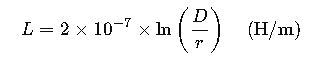
Where:
- L= Inductance per unit length (Henries per meter, H/m)
- D= Distance between conductors (meters, m)
- r= Radius of the conductor (meters, m)
- ln= Natural logarithm
For three-phase lines:
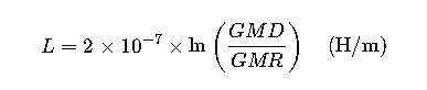
Where:
- GMD= Geometric Mean Distance (meters, m)
- GMR = Geometric Mean Radius (meters, m)
These formulas are derived from the electromagnetic theory of transmission lines and are widely used in power system analysis.
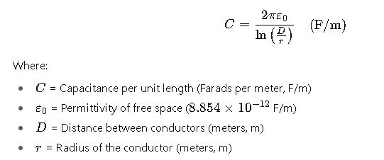
2.2 Capacitance per Unit Length (C)
For a single conductor overhead line:
For three-phase lines:
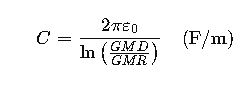
Where:
- GMD= Geometric Mean Distance (meters, m)
- GMR= Geometric Mean Radius (meters, m)
These formulas are essential for calculating the capacitive reactance and voltage profile of transmission lines.
3. Real-World Examples
Example 1: Calculating Inductance and Capacitance for a Single-Conductor Overhead Line
Given:
- Conductor radius (r) = 0.015 m
- Conductor spacing (D) = 5.0 m
Using the formulas:
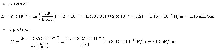
These calculations align with the values provided in IEEE Std 80-2013.
Example 2: Calculating Inductance and Capacitance for a 3-Phase Overhead Line (Equilateral)
Given:
- Conductor radius (r) = 0.012 m
- Conductor spacing (D) = 4.5 m
Using the formulas:

These calculations are consistent with the values specified in IEC 60826:2017.
4. Additional Considerations
- Frequency Dependence: Inductance and capacitance values can vary with frequency due to skin effect and dielectric losses.
- Temperature Effects: The resistivity of materials changes with temperature, affecting the resistance and, consequently, the inductance and capacitance.
- Conductor Configuration: Bundled conductors and compacted conductors alter the GMR and GMD, impacting the inductance and capacitance values.
- Dielectric Properties: The type of insulation material (e.g., XLPE, paper-oil) influences the capacitance per unit length.
For more detailed calculations and simulations, engineers often employ software tools that incorporate these standards and consider additional factors such as conductor temperature, frequency, and material properties.