The short-circuit withstand capacity of conductors is vital in electrical engineering, ensuring safety, reliability, and compliance. IEC 60949 and IEC 60364-5-54 define methods to calculate adiabatic capacity, verifying conductors withstand stresses.
Conductor Short-Circuit Capacity Calculator — IEC (adiabatic)
Estimate thermally permissible short-circuit current using the adiabatic equation. Enter conductor area (S), fault duration (t) and choose material/insulation (or enter custom k).
Which formula is used?
Where do the k values come from?
When should I not use the adiabatic equation?
Core Formula for Short-Circuit Capacity (IEC)
The main formula from IEC 60949 (and referenced in IEC 60364) is the adiabatic equation:
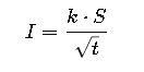
Where:
- I = permissible short-circuit current (A)
- k = material constant depending on conductor material and insulation (A·√s / mm²)
- S = cross-sectional area of the conductor (mm²)
- t = duration of short-circuit (s)
Detailed Explanation of Variables
- Conductor Cross-Section (S, in mm²):
- Determines thermal mass and ability to withstand heat.
- Common sizes: 1.5, 2.5, 4, 6, 10, 16, 25, 35, 50, 70, 95, 120, 150, 185, 240, 300, 400, 500, 630 mm².
- Time (t, in seconds):
- Represents fault clearing time.
- Typical ranges:
- LV breakers/fuses: 0.1 – 1 s
- MV/HV relays: 0.2 – 3 s
- Emergency/back-up scenarios: up to 5 s
- Material Constant (k):
- Derived from material resistivity, specific heat, and permissible final temperature.
- Common k-values (IEC 60364-5-54):
| Material & Insulation Type | Initial Temp (°C) | Final Temp (°C) | k (A·√s/mm²) |
|---|---|---|---|
| Copper, PVC | 70 | 160 | 115 |
| Copper, XLPE | 90 | 250 | 143 |
| Aluminium, PVC | 70 | 160 | 76 |
| Aluminium, XLPE | 90 | 250 | 94 |
| Bare copper (earth) | 30 | 250 | 226 |
Reference: IEC 60364-5-54
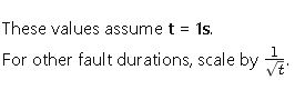
Extended Data Table: Conductor Short-Circuit Capacity (1s Fault Duration)
The following table provides allowable short-circuit current (I) for common conductor sizes, for 1s fault duration, calculated using IEC k-values.
| Cross-Section (mm²) | Copper PVC (k=115) | Copper XLPE (k=143) | Aluminium PVC (k=76) | Aluminium XLPE (k=94) |
|---|---|---|---|---|
| 1.5 | 173 A | 220 A | 114 A | 141 A |
| 2.5 | 288 A | 358 A | 190 A | 235 A |
| 4 | 460 A | 572 A | 304 A | 376 A |
| 6 | 690 A | 858 A | 456 A | 576 A |
| 10 | 1150 A | 1430 A | 760 A | 940 A |
| 16 | 1840 A | 2290 A | 1216 A | 1504 A |
| 25 | 2875 A | 3575 A | 1900 A | 2350 A |
| 35 | 4025 A | 5005 A | 2660 A | 3290 A |
| 50 | 5750 A | 7150 A | 3800 A | 4700 A |
| 70 | 8050 A | 10,010 A | 5320 A | 6580 A |
| 95 | 10,925 A | 13,585 A | 7220 A | 8930 A |
| 120 | 13,800 A | 17,160 A | 9120 A | 11,280 A |
| 150 | 17,250 A | 21,450 A | 11,400 A | 14,100 A |
| 185 | 21,275 A | 26,455 A | 14,060 A | 17,390 A |
| 240 | 27,600 A | 34,320 A | 18,240 A | 22,560 A |
| 300 | 34,500 A | 42,900 A | 22,800 A | 28,200 A |
| 400 | 46,000 A | 57,200 A | 30,400 A | 37,600 A |
| 500 | 57,500 A | 71,500 A | 38,000 A | 47,000 A |
| 630 | 72,450 A | 90,090 A | 47,880 A | 59,220 A |
Step-by-Step Real-World Examples
Case Study 1: LV Distribution Cable (Copper XLPE)
Scenario:
- 3-phase, 400V LV distribution board.
- Conductor: Copper XLPE, 70 mm².
- Fault clearing time: 0.5 s.
Solution:
1.From table: 70 mm², Copper XLPE = 10,010 A (for 1s).
2.For 0.5s:
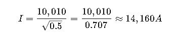
3.The cable withstands 14.16 kA for 0.5s.
4.If the expected short-circuit level at the board is 12 kA, conductor sizing is adequate.
Case Study 2: MV Aluminium Conductor (XLPE)
Scenario:
- 11kV feeder, expected short-circuit level 8 kA.
- Protection relay trips within 1.5s.
- Conductor: Aluminium XLPE, 185 mm².
Solution:
1.From table: 185 mm² Aluminium XLPE = 17,390 A (for 1s).
2.For 1.5s:
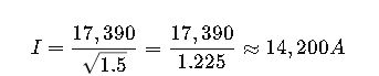
3.Allowable withstand = 14.2 kA for 1.5s.
4.Since required withstand is 8 kA, conductor is more than sufficient.
Engineering Considerations Beyond the Adiabatic Equation
- Non-Adiabatic Conditions:
- For fault durations < 0.1 s, mechanical forces may dominate instead of thermal effects.
- Parallel Conductors:
- Each conductor must be evaluated independently.
- Unequal current distribution may reduce actual withstand.
- Earthing Conductors:
- Earth conductors often use bare copper, with higher k-values.
- Derating Factors:
- High ambient temperature.
- Grouping of cables.
- Soil resistivity in buried installations.
- Verification Against Protection Devices:
- Must ensure I²t clearing characteristic of fuse or breaker matches conductor withstand.
- Reference: IEC 60909 – Short-Circuit Currents
Extended Tables for Multiple Fault Durations
Because fault clearing times vary widely depending on system voltage, protection scheme, and breaker technology, engineers must verify conductors under different durations. Below are ready-to-use tables derived from IEC k-values.
Copper XLPE Insulated Conductors (k = 143)
| Cross-Section (mm²) | 0.2s | 0.5s | 1s | 3s | 5s |
|---|---|---|---|---|---|
| 16 | 5124 A | 3220 A | 2290 A | 1323 A | 1024 A |
| 35 | 11,122 A | 6992 A | 5005 A | 2890 A | 2237 A |
| 70 | 22,223 A | 13,991 A | 10,010 A | 5779 A | 4470 A |
| 120 | 38,134 A | 24,007 A | 17,160 A | 9910 A | 7667 A |
| 185 | 58,818 A | 37,000 A | 26,455 A | 15,262 A | 11,818 A |
| 300 | 95,050 A | 59,985 A | 42,900 A | 24,767 A | 19,028 A |
| 500 | 158,300 A | 99,850 A | 71,500 A | 41,300 A | 31,900 A |
Aluminium XLPE Insulated Conductors (k = 94)
| Cross-Section (mm²) | 0.2s | 0.5s | 1s | 3s | 5s |
|---|---|---|---|---|---|
| 25 | 6160 A | 3876 A | 2740 A | 1582 A | |
| 50 | 12,320 A | 7752 A | 5480 A | 3164 A | 2450 A |
| 95 | 23,400 A | 14,730 A | 10,430 A | 6020 A | 4660 A |
| 150 | 37,000 A | 23,300 A | 16,520 A | 9540 A | 7370 A |
| 240 | 59,200 A | 37,250 A | 26,400 A | 15,250 A | 11,800 A |
| 400 | 98,700 A | 62,150 A | 44,000 A | 25,400 A | 19,600 A |
| 630 | 155,400 A | 97,900 A | 69,300 A | 40,000 A | 30,900 A |
These values are practical look-up references for protection coordination and quick engineering checks.
Practical Engineering Applications
Industrial Low-Voltage Switchgear
- Challenge: In LV systems, fault levels can reach 30–50 kA at the busbars.
- Role of calculator: Ensures that outgoing feeder cables and busbars can thermally survive faults until breakers clear them.
- Typical case: 240 mm² copper XLPE cables feeding MCCs withstand up to ~34 kA for 1s, sufficient for modern LV switchgear fault ratings.
Medium-Voltage Distribution Networks
- Challenge: Fault levels are usually between 5–25 kA, but protection times are longer (1–3s).
- Role of calculator: Conductors must be checked not only for magnitude but also duration.
- Typical case: An 11kV feeder with aluminium 185 mm² XLPE can withstand ~14 kA for 1.5s, covering most distribution networks.
Earthing and Grounding Conductors
- Challenge: Earthing conductors must dissipate energy safely during earth faults without damage.
- Special case: Bare copper conductors with k = 226 have very high withstand capacity.
- Example: A 70 mm² bare copper earthing conductor can handle over 18 kA for 1s.
Renewable Energy Systems (Solar & Wind Farms)
- Challenge: Short-circuit contribution from inverters is typically lower, but clearing times are longer.
- Example: PV farms may use aluminium conductors with higher lengths, requiring careful IEC calculation to avoid overheating during prolonged faults.
Common Mistakes in Short-Circuit Capacity Evaluation
- Ignoring protection clearing time:
- Engineers often check only for 1s, but many relays clear in 0.2–0.5s, meaning cables can safely handle higher currents.
- Overestimating parallel conductor capacity:
- Current sharing may not be equal, especially in asymmetric layouts.
- Forgetting earthing conductors:
- Earth faults may last longer, stressing earth conductors more than phase conductors.
- Not matching with protective device curves:
- Conductors must always be verified against I²t clearing energy of the breaker or fuse.